
A4 Mk3
 Note
Note
|
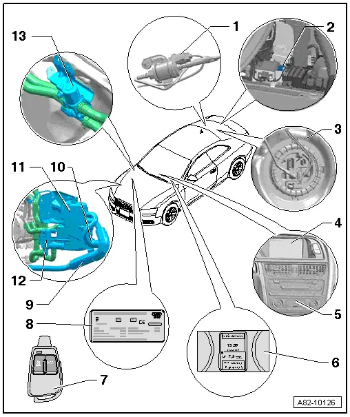
| 1 - | Metering pump -V54- |
| q | Removing and installing → Chapter |
| q | Diverting fuel for auxiliary heater → Chapter |
| q | Checking fuel delivery rate → Chapter. |
| q | Checking actuation → Vehicle diagnostic, testing and information systemVAS 5051/, “Guided fault-finding function”. |
| q | Checking wiring → Vehicle diagnostic, testing and information systemVAS 5051/, “Guided fault-finding function”. |
| q | Depending on the model, the vehicle may be fitted with noise insulation in the fuel pipe to the auxiliary heater in the area of the metering pump -V54- to reduce noise → Chapter. |
| 2 - | Auxiliary heating radio controlled receiver -R64- |
| q | Fitting location → Chapter |
| q | Removing and installing → Electrical system; Rep. Gr.91. |
| q | There are different versions of the remote control receiver for auxiliary heater -R64- → Electronic parts catalogue. |
| 3 - | Fuel delivery unit with connection for diverting fuel for the auxiliary heater |
| q | Different fuel delivery units depending on vehicle model (petrol or diesel engine, FWD or 4WD) → Fuel supply system; Rep. Gr.20. |
| q | Diverting fuel for auxiliary heater → Chapter |
Note| After removing and installing fuel system components, the auxiliary heater is to be switched on and operated at full load for at least 10 minutes to ensure complete bleeding of the fuel pipe. |
| 4 - | Multi Media Interface (MMI) |
| q | The various auxiliary heating and auxiliary ventilation actuation functions are entered via the MMI and indicated on the corresponding display → Chapter. |
| q | MMI operation of the auxiliary heater (in the “Car” menu of the Multi Media Interface) and the corresponding displays are described in the relevant operating instructions → Infotainment / MMI operating instructions. |
| q | If there is insufficient fuel in the fuel tank (fuel gauge in red zone), the auxiliary heater cannot be switched on (the tick in the MMI for the “Immediate auxiliary heater activation” function and the symbol for auxiliary heater mode in the clock cannot be activated or go out again) → Owner's manual and → Infotainment / MMI operating instructions. |
Note| t | The Audi A5 Coupé and the Audi A4 as of Model Year 2009 are gradually being fitted with modified operating and display units, Climatronic control unit -J255- (these were installed on the Audi Q5 right from the start of production) → Electronic parts catalogue and → Air conditioning; Rep. Gr.87. On these operating and display units, display of the additional auxiliary heater and air conditioner functions is governed by the encoding of the operating and display unit, Climatronic control unit -J255-. In the event of incorrect assignment and encoding, the various auxiliary heater and air conditioner functions cannot be displayed in the MMI and selected → Vehicle diagnostic, testing and information systemVAS 5051/, “Guided fault-finding function”, → Owner's manual and → operating instructions for “Infotainment / MMI”. |
| t | Depending on the version of the control units concerned and the encoding of the operating and display unit, Climatronic control unit -J255-, the additional auxiliary heater and air conditioner functions are selected and activated by way of the rotary knob/pushbutton of the -J255- or the MMI operating unit → Owner's manual and → operating instructions for “Infotainment / MMI”. |
| t | Pay attention to correct assignment and encoding of the operating and display unit, Climatronic control unit -J255- e.g. for the control unit for front display and information control panel -J523- or the control unit 1 for information electronics -J794- → Electronic parts catalogue (different versions). In the event of incorrect assignment, the various auxiliary heater and air conditioner functions cannot be displayed in the MMI and selected. |
| 5 - | Operating and display unit, Climatronic control unit -J255- |
| q | Actuated by way of the data bus. |
| q | When operating the auxiliary heater by way of the “Timer” function or remote control, this determines the mode in which the auxiliary heater starts up (auxiliary ventilation or auxiliary heating) → Air conditioning; Rep. Gr.87 and → Vehicle diagnostic, testing and information systemVAS 5051/, “Guided fault-finding function”. |
| q | For the auxiliary heater to be activated by way of the “Timer” function or remote control (hand transmitter), a temperature greater than “Lo” must have been set on the operating and display unit, Climatronic control unit -J255-. |
| q | To de-ice the windows as quickly as possible, it is appropriate to set as high a temperature as possible on the operating and display unit, Climatronic control unit -J255- before switching off the ignition. The operating and display unit, Climatronic control unit -J255- adopts the last temperature set in auxiliary heating mode and regulates the passenger compartment temperature in line with the specified temperature set. |
Note| t | The Audi A5 Coupé and the Audi A4 as of Model Year 2009 are gradually being fitted with modified operating and display units, Climatronic control unit -J255- (these were installed on the Audi Q5 right from the start of production). Pay attention to correct assignment of the components and correct encoding → Item, → Electronic parts catalogue and → Air conditioning; Rep. Gr.87. |
| t | As of Model Year 2010 a start/stop system will be available as an optional extra for this vehicle in conjunction with certain engines. On these vehicles, pay attention to the correct version of the air conditioner operating and display unit, Climatronic control unit -J255- and of the auxiliary heater → Electronic parts catalogue and → "Guided fault-finding" function of vehicle diagnostic, testing and information system VAS 5051. |
| t | On vehicles with a start/stop system the circulation pump -V55- of the auxiliary heater is actuated during the stop function by the supplementary heater control unit -J364-. Via the data bus, -J364- is requested by the air conditioner operating and display unit, Climatronic control unit -J255- to switch on -V55- → "Guided fault-finding" function of vehicle diagnostic, testing and information system VAS 5051 |
| t | Depending on the mode of operation set (“Auxiliary heating” or “Auxiliary ventilation”), certain faults which impair the auxiliary heating / auxiliary ventilation function are not stored in the event recorder of the auxiliary heater control unit -J364-. In the event of problems with the auxiliary heater, the event recorder of the operating and display unit, Climatronic control unit -J255- should therefore also be read out → Vehicle diagnostic, testing and information systemVAS 5051/, “Guided fault-finding function”. |
| 6 - | Display in dash panel insert |
| q | Installed in dash panel insert |
| q | Depending on the version, the “Auxiliary heater” optional extra must have been adapted by way of the “Adaption” function in the control unit in dash panel insert -J285- → Vehicle diagnostic, testing and information systemVAS 5051/, “Guided fault-finding function”. |
| q | If there is insufficient fuel in the tank (fuel gauge in red zone), the auxiliary heater cannot be switched on (the tick in the MMI for the “Immediate auxiliary heater activation” function and the symbol for auxiliary heater mode in the clock cannot be activated or go out again) → Vehicle diagnostic, testing and information systemVAS 5051/, “Guided fault-finding function”, → Owner's manual and → Infotainment / MMI operating instructions. |
| q | Depending on the operating status of the auxiliary heater (auxiliary heating/auxiliary ventilation mode) or if the timer function has been selected, one of the symbols for auxiliary heating/auxiliary ventilation is permanently actuated or both symbols flash → Owner's manual and → Infotainment / MMI operating instructions. |
| q | If the vehicle is fitted with remote control for the auxiliary heater (as optional extra), this actuates the supplementary heater control unit -J364-. The control unit then transmits the information “Activate or deactivate auxiliary heating/auxiliary ventilation” via the data bus to the operating and display unit, Climatronic control unit -J255-. The operating and display unit then decides whether auxiliary heating mode is required to attain the specified temperature set or whether auxiliary ventilation mode is sufficient. |
| 7 - | Auxiliary heater remote control |
| q | For activating and deactivating the “auxiliary heating” or “auxiliary ventilation” function of the auxiliary heater → Chapter. |
| q | Pressing the buttons causes the integral indicator lamp to light or flash → Owner's manual. |
| q | Replacing batteries → Chapter |
| q | The corresponding button must be pressed for at least 3 seconds to enable the remote control to detect pressing of the buttons and transmit a radio signal → Owner's manual. |
| q | If the auxiliary heater is replaced together with the supplementary heater control unit -J364-, check the operation of at least one hand transmitter and re-adapt all hand transmitters if necessary → Chapter and → Vehicle diagnostic, testing and information systemVAS 5051/, “Guided fault-finding function”. |
| q | After removing the batteries → Chapter, the remote control unit model can be seen from the sticker with the part number → Electronic parts catalogue. |
Note| t | Depending on the mode of operation set (“Auxiliary heating” or “Auxiliary ventilation”), certain faults which impair the auxiliary heating / auxiliary ventilation function are not stored in the event recorder of the auxiliary heater control unit -J364-. In the event of problems with the auxiliary heater, the event recorder of the operating and display unit, Climatronic control unit -J255- should therefore also be read out → Vehicle diagnostic, testing and information systemVAS 5051/, “Guided fault-finding function”. |
| t | The Audi A4, A5 and Q5 are currently provided with an auxiliary heater remote control hand transmitter with no display → Owner's manual. |
| t | Auxiliary heaters with an auxiliary heater control unit -J364- with part number 8xx xxx. xxx are only designed for actuation by way of a hand transmitter with no display. As of 10.2010, auxiliary heaters with a -J364- with part number 4xx xxx xxx are gradually being introduced. With these auxiliary heaters, the version of the hand transmitter (with or without display) must have been properly encoded in -J364-. This also applies to service replacement of a -J364- with part number 8xx xxx xxx by a -J364- with part number 4xx xxx xxx → Vehicle diagnostic, testing and information systemVAS 5051/, “Guided fault-finding function” |
| t | Pay attention to correct assignment of the auxiliary heater remote control hand transmitter to the remote control receiver for auxiliary heater -R64- (different versions for hand transmitter without and with display) as well as to correct assignment and encoding of -J364- → Electronic parts catalogue and → Vehicle diagnostic, testing and information systemVAS 5051/, “Guided fault-finding function”. |
| 8 - | Duplicate plate for auxiliary heater |
| q | Indicates both technical data and auxiliary heater model. |
| q | Bonded from inside to the bonnet |
| 9 - | Auxiliary heater exhaust silencer |
| q | Removing and installing → Chapter |
| 10 - | Intake air noise insulation |
| q | Removing and installing → Chapter |
| 11 - | Auxiliary heater |
| q | Removing and installing → Chapter |
| q | Incorporation into coolant circuit → Chapter |
| q | Dismantling and assembling → Chapter |
| q | Checking electrical components of auxiliary heater → Vehicle diagnostic, testing and information systemVAS 5051/, “Guided fault-finding function” and → Chapter. |
| q | Block diagram of auxiliary heater → Chapter |
Note| t | On replacement, pay attention to correct version (different models for petrol and diesel) → Chapter and → Electronic Parts Catalogue. |
| t | The Audi A5 Coupé and the Audi A4 as of Model Year 2009 are gradually being fitted with modified auxiliary heaters with an adapted supplementary heater control unit -J364- (these were installed on the Audi Q5 right from the start of production). Pay attention to correct assignment of these components to the vehicle → Electronic parts catalogue and → Vehicle diagnostic, testing and information systemVAS 5051/, “Guided fault-finding function”. |
| t | This auxiliary heater is installed in various vehicle models. The part number changes each time this auxiliary heater is fitted in a new vehicle model (e.g. from 8K0 xxx xxx to 8R0 xxx xxx on introduction of the Audi Q5 and subsequently to 4xx xxx xxx etc.). Attention must therefore be paid to correct assignment. Care must however also be taken to ensure that an old auxiliary heater version is never installed in a vehicle previously fitted with a newer version. For example, an Audi A4 provided at the factory with an auxiliary heater with part number 8R0 xxx xxx is not to be fitted with an auxiliary heater with part number 8K0 xxx xxx → Electronic parts catalogue. |
| t | As of 10.2010 auxiliary heaters with part number 4xx xxx xxx are gradually to be introduced. Service installation of this version of the auxiliary heater is also possible in vehicles originally fitted with an auxiliary heater with part number 8R0 xxx xxx or 8K0 xxx xxx. As however there are differences between certain components of the various auxiliary heater versions (e.g. the 2-pin connector for the power supply to the auxiliary heater control unit -J364-), attention must be paid to correct assignment when replacing individual components of the auxiliary heater → Electronic parts catalogue. |
| t | If an auxiliary heater with part number 4xx xxx xxx is fitted, attention must also be paid with this version to correct encoding for the vehicle concerned and the remote control hand transmitter provided (no display at present). Different functions are stored in the control unit depending on the type of vehicle encoded → Electronic parts catalogue and → "Guided fault-finding" function of vehicle diagnostic, testing and information system VAS 5051. |
| t | The holders for the auxiliary heater were gradually modified on the Audi Q5 in Model Year 2009. Pay attention to the correct assignment when replacing the auxiliary heater and holders → Electronic parts catalogue and → Anchor. |
| t | As of Model Year 2010 a start/stop system will be available as an optional extra for this vehicle in conjunction with certain engines. On these vehicles, pay attention to the correct version of the air conditioner operating and display unit, Climatronic control unit -J255- and of the auxiliary heater → Electronic parts catalogue and → "Guided fault-finding" function of vehicle diagnostic, testing and information system VAS 5051. |
| t | Vehicles with a start/stop system are not to be fitted with auxiliary heaters with part number 8K0 xxx xxx → Electronic parts catalogue and → "Guided fault-finding" function of vehicle diagnostic, testing and information system VAS 5051. |
| t | On vehicles with a start/stop system the circulation pump -V55- of the auxiliary heater is actuated during the stop function by the supplementary heater control unit -J364-. Via the data bus, -J364- is requested by the air conditioner operating and display unit, Climatronic control unit -J255- to switch on -V55- → "Guided fault-finding" function of vehicle diagnostic, testing and information system VAS 5051 |
| t | If the auxiliary heater or the supplementary heater control unit -J364- is replaced, check the operation of at least one hand transmitter and re-adapt all hand transmitters if necessary → Chapter and → Vehicle diagnostic, testing and information systemVAS 5051/, “Guided fault-finding function”. |
| t | Checking power supply → Vehicle diagnostic, testing and information systemVAS 5051/, “Guided fault-finding function” and → Chapter. |
| t | If, following replacement of the auxiliary heater or the supplementary heater control unit -J364-, the fault “Incorrect control unit fitted” is displayed, check that -J364- has been encoded for the correct type of fuel “Diesel” or “Petrol” and correct if necessary → "Guided fault-finding" function of vehicle diagnostic, testing and information system VAS 5051. |
| t | Depending on the mode of operation set (“Auxiliary heating” or “Auxiliary ventilation”), certain faults which impair the auxiliary heating / auxiliary ventilation function are not stored in the event recorder of the auxiliary heater control unit -J364-. In the event of problems with the auxiliary heater, the event recorder of the operating and display unit, Climatronic control unit -J255- should therefore also be read out → Vehicle diagnostic, testing and information systemVAS 5051/, “Guided fault-finding function”. |
| The auxiliary heater is fitted with the following electrical components: |
| t | Supplementary heater control unit -J364- |
| t | Temperature sensor -G18- |
| t | Flame monitor -G64-. |
| t | Supplementary and auxiliary heater temperature sensor 2 -G587-. |
| t | Glow plug for heater -Q9-. |
| t | Combustion air blower -V6- |
| t | Fuel pre-heating heater element -Z66-. |
| 12 - | Circulation pump -V55- |
| q | The circulation pump -V55- is actuated by the supplementary heater control unit -J364- → Current flow diagrams, Electrical fault finding and Fitting locations and → Vehicle diagnostic, testing and information systemVAS 5051/, “Guided fault-finding function”. |
| q | Removing and installing → Chapter |
| q | Depending on vehicle equipment, the supplementary heater control unit -J364- may activate the circulation pump -V55- even when the auxiliary heater is switched off on account of a request received via the data bus (e.g. request from engine control unit or operating and display unit, Climatronic control unit -J255-). |
Note| t | Vehicles with a start/stop system are not to be fitted with auxiliary heaters with part number 8K0 xxx xxx → Electronic parts catalogue and → "Guided fault-finding" function of vehicle diagnostic, testing and information system VAS 5051. |
| t | On vehicles with a start/stop system the circulation pump -V55- of the auxiliary heater is actuated during the stop function by the supplementary heater control unit -J364-. Via the data bus, -J364- is requested by the air conditioner operating and display unit, Climatronic control unit -J255- to switch on -V55- → "Guided fault-finding" function of vehicle diagnostic, testing and information system VAS 5051 |
| 13 - | Heater coolant shut-off valve -N279- |
| q | Actuated in auxiliary heating mode by the supplementary heater control unit -J364-. |
| q | On vehicles with a 4 or 6-cyl. petrol engine, the heater coolant shut-off valve -N279- can also be actuated with the auxiliary heater switched off (e.g. with certain settings on the operating and display unit, Climatronic control unit -J255- to shut off the coolant supply to the heat exchanger of the air conditioner unit). |
| q | Different versions (for Audi A5 Coupé, Audi A4 and Audi Q5); pay attention to correct assignment → Electronic parts catalogue. |
Note| t | To stop the flow of coolant from the cylinder head being completely interrupted with the engine running and -N279- actuated, certain vehicles are fitted with a non-return valve in the coolant circuit → Chapter. |
| t | On the Audi Q5, actuation of -N279- is only permissible up to a certain engine speed (currently up to approx. 1200 rpm). Attention is therefore to be paid to the correct version, encoding and adaption of the auxiliary heater → Vehicle diagnostic, testing and information systemVAS 5051/, “Guided fault-finding function”. |
| q | Removing and installing → Chapter |
| q | Checking wiring → Vehicle diagnostic, testing and information systemVAS 5051/, “Guided fault-finding function” and → Chapter. |
| q | Operation → Chapter |