
A4 Mk3
| Exploded view of auxiliary heater components |
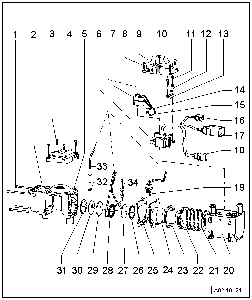
| 1 - | Bolt M5×80 |
| q | 4x |
| q | Tightening torque 6 Nm |
| 2 - | Cover for combustion air blower -V6- |
| 3 - | Bolt M4×16 |
| q | 4x |
| q | Tightening torque 3 Nm |
| 4 - | Cover for combustion air blower -V6- |
| 5 - | Combustion air blower -V6- |
| q | Replacing → Chapter |
| q | Not to be further dismantled |
| 6 - | Supplementary heater control unit -J364- |
| q | Removing and installing → Chapter |
 Note
Note| t | This auxiliary heater is installed in various vehicle models. The part number changes each time this auxiliary heater is fitted in a new vehicle model (e.g. from 8K0 xxx xxx to 8R0 xxx xxx on introduction of the Audi Q5 and subsequently to 4xx xxx xxx etc.). Attention must therefore be paid to correct assignment. Care must however also be taken to ensure that an old auxiliary heater version is never installed in a vehicle previously fitted with a newer version. For example, an Audi A4 provided at the factory with an auxiliary heater with part number 8R0 xxx xxx is not to be fitted with an auxiliary heater with part number 8K0 xxx xxx → Electronic parts catalogue. |
| t | As of 10.2010 auxiliary heaters with part number 4xx xxx xxx are gradually to be introduced. Service installation of this version of the auxiliary heater is also possible in vehicles originally fitted with an auxiliary heater with part number 8R0 xxx xxx or 8K0 xxx xxx. As however there are differences between certain components of the various auxiliary heater versions (e.g. the 2-pin connector for the power supply to the auxiliary heater control unit -J364-), attention must be paid to correct assignment when replacing individual components of the auxiliary heater → Electronic parts catalogue. |
| t | If an auxiliary heater with part number 4xx xxx xxx is fitted, attention must also be paid with this version to correct encoding for the vehicle concerned and the remote control unit provided (different functions are stored in the control unit depending on the type of vehicle encoded and the remote control unit version) → Electronic parts catalogue and → Vehicle diagnostic, testing and information systemVAS 5051/, “Guided fault-finding function”. |
| t | There are different versions of the retaining clip for the temperature sensor -G18- and the temperature sensor 2 for supplementary and auxiliary heating -G587-. A -J364- with part number 8xx xxx xxx is only to be fitted with retaining clips with no spacer ring. A -J364- with part number 4xx xxx xxx is only to be fitted with retaining clips with a spacer ring. Attention is therefore to be paid to correct assignment (matching part numbers of retaining clip and auxiliary heater control unit -J364-) → Chapter and → Electronic parts catalogue. |
 Caution
|
| 7 - | 14-pin connector at auxiliary heater control unit |
| Contact assignment and wiring colours: |
| t | Temperature sensor -G18-: Contact 10 - black, contact 11 - black. |
| t | Flame monitor -G64-: Contact 1 - brown, contact 2 - brown. |
| t | Temperature sensor 2 for supplementary and auxiliary heating -G587-: Contact 7 - white, contact 8 - white. |
| t | Glow plug for heater -Q9-: Contact 3 - brown, contact 6 - white. |
| t | Combustion air blower -V6-: Contact 13 - black, contact 14 - brown. |
| t | Fuel pre-heating heater element -Z66-: Contact 9 - black, contact 12 - black. |
| 8 - | Bolt M4×16 |
| q | 4x |
| q | Tightening torque 3 Nm |
| 9 - | Clip |
| q | For pipe penetration |
| 10 - | Cover for supplementary heater control unit -J364- |
Note| There are different versions of this cover. Pay attention to correct assignment (different versions for a -J364- with part number 8xx xxx xxx and 4xx xxx xxx) → Electronic parts catalogue. |
| 11 - | Bolt M4×12 |
| q | Tightening torque 3 Nm |
| 12 - | Retaining clip |
| q | For temperature sensor -G18- |
Note| There are different versions of the retaining clip for the temperature sensor -G18- and the temperature sensor 2 for supplementary and auxiliary heating -G587-. A -J364- with part number 8xx xxx xxx is only to be fitted with retaining clips with no spacer ring. A -J364- with part number 4xx xxx xxx is only to be fitted with retaining clips with a spacer ring. Attention is therefore to be paid to correct assignment (matching part numbers of retaining clip and auxiliary heater control unit -J364-) → Electronic parts catalogue. |
Caution
|
| 13 - | Retaining clip |
| q | For supplementary and auxiliary heater temperature sensor 2 -G587- |
Note| There are different versions of the retaining clip for the temperature sensor -G18- and the temperature sensor 2 for supplementary and auxiliary heating -G587-. A -J364- with part number 8xx xxx xxx is only to be fitted with retaining clips with no spacer ring. A -J364- with part number 4xx xxx xxx is only to be fitted with retaining clips with a spacer ring. Attention is therefore to be paid to correct assignment (matching part numbers of retaining clip and auxiliary heater control unit -J364-) → Electronic parts catalogue. |
Caution
|
| 14 - | Temperature sensor -G18- |
| q | Removing and installing → Chapter |
| q | Checking → Chapter |
| 15 - | Supplementary and auxiliary heater temperature sensor 2 -G587- |
| q | Removing and installing → Chapter |
| q | Checking → Chapter |
| 16 - | 2-pin connector |
| q | To circulation pump -V55- |
| 17 - | 6-pin connector |
| q | To supplementary heater control unit -J364- |
| 18 - | 2-pin connector |
| q | For power supply |
Note| Different versions → Item |
| 19 - | Glow plug for heater -Q9- |
| q | Rated voltage: 8 V |
| q | Removing and installing → Chapter |
| q | Checking → Chapter |
| q | If applicable, carefully clean the glow element with a brass wire brush (spark plug brush). |
Note| There are different versions of the glow plug for heater -Q9-. Pay attention to correct assignment → Electronic parts catalogue. |
| 20 - | Water jacket |
| q | If applicable, clean the inside and outside with a brass wire brush (spark plug brush). |
| 21 - | Heat exchanger |
| q | Removing and installing → Chapter |
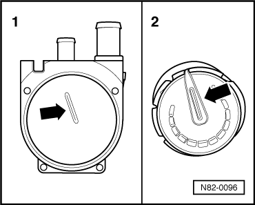
| q | Pay attention to installation position → Fig. |
| q | If applicable, clean the inside and outside with a brass wire brush (spark plug brush). |
| 22 - | O-ring |
| q | Replace |
| q | Moisten with a small quantity of coolant when fitting. |
| 23 - | Seal |
| q | Replace |
| 24 - | Burner element |
| q | If applicable, clean the inside and outside with a brass wire brush (spark plug brush). |
| q | Different versions (for petrol and diesel) → Electronic parts catalogue |
| 25 - | Moulded gasket |
| q | Replace |
| 26 - | Seal |
| q | Replace |
| 27 - | Fuel evaporator |
| q | Removing and installing → Chapter |
| q | Different versions (for petrol and diesel) → Electronic parts catalogue |
| 28 - | Fuel pre-heating heater element -Z66- |
| q | Removing and installing → Chapter |
| q | Checking → Chapter |
| 29 - | Seal |
| q | Replace |
| 30 - | Washer |
| 31 - | Circlip |
| 32 - | Graphite seal |
| q | Replace |
| q | Pay attention to installation position → Anchor |
| 33 - | Flame monitor -G64- |
| q | Removing and installing → Chapter |
| q | Checking → Chapter |
| 34 - | Clip |
| q | Only provided for petrol heater (attached to fuel pipe of fuel evaporator) |
|
|