audi Workshop Repair Guides

Audi Workshop Service and Repair Manuals

Installing gearbox - vehicles with 3.0 ltr. TDI engine > < Installing gearbox - vehicles with 4.2 ltr. FSI engine
Removing gearbox - vehicles with 3.0 ltr. TDI engine
   
Removing gearbox - vehicles with 3.0 ltr. TDI engine
Special tools and workshop equipment required
t  Used oil collection and extraction unit -V.A.G 1782-
t  Engine bung set -VAS 6122-
t  Counterhold tool -T10172- with -T10172/5-
t  Adapter -T40058-
t  Gearbox support -T40173-

   
t  Support bracket -10 - 222 A-
  W00-0225
t  Removal lever -80 - 200-
  W00-0353
t  Engine and gearbox jack -V.A.G 1383 A-
  W00-0120
t  Stepladder -VAS 5085-
Removing
–  Bring wheels into straight-ahead position.
–  Switch off ignition and take out ignition key.
  Caution
When disconnecting the battery there is a risk of serious damage to electronic components:
Observe the correct procedure for disconnecting the battery.
–  Disconnect battery → Electrical system; Rep. Gr.27.
–  Remove particulate filter and front exhaust pipe → Rep. Gr.26.
–  Remove both front wheels.
  W00-0713
–  Remove cover -1- for drive shaft from wheel housing (both sides).
  A10-10179
–  Remove front noise insulation → General body repairs, exterior; Rep. Gr.66.
  A10-10912
–  Remove bolt -arrow- for ATF pipes -1- and -2-.
  Note
  A37-10858
Place a cloth below the connection to catch escaping ATF.
–  Remove bolts -1- and -2-, detach ATF pipes from gearbox and tie up.
–  Seal off open lines and connections with clean plugs from engine bung set -VAS 6122-.
  A37-10743
–  Remove bolts -2 … 5- securing gearbox to engine (accessible from above).
  A34-10370
–  Remove bolt -1- for engine lifting eye.
–  Move electrical wiring harness clear -arrow- using removal lever -80 - 200-.
  Note
-Item 2- can be disregarded.
  A15-10476
–  Set up support bracket -10 - 222 A- on suspension turrets (left and right), as shown in illustration.
–  Hook spindle -10 - 222 A /11- onto engine lifting eye (left-side).
  A34-10578
–  Remove bolts -1, 2, 3- and detach heat shield -A- for drive shaft (right-side).
  Note
-Item B- can be disregarded.
–  Unbolt drive shafts (left and right) from flange shafts on gearbox.
  A37-10857
  Caution
The gearbox control unit (mechatronic unit) can be damaged by electrostatic discharge.
Do not touch contact pins in gearbox connector with bare hands.
–  Touch gearbox housing with your hand (without gloves) to discharge any static electricity.
–  Turn fastener anti-clockwise -arrow- and unplug electrical connector on gearbox.
–  Move wiring harness clear on gearbox.
  A37-10859
–  Remove nut -1- for hydraulic line for power steering.
  Caution
Risk of damage to parts of the running gear.
Do not let the vehicle down on the wheels if the gearbox mounting, steering box or subframe cross brace are not properly installed.
–  Remove bolts -arrows- and detach subframe cross brace.
  A40-10133
–  Disconnect electrical connector -2- for engine speed sender -G28- and move wiring clear.
  Note
-Item 1- can be disregarded.
  A10-10869
–  Use removal lever -80 - 200- to pry ball socket -1- on selector lever cable off selector shaft lever.
–  Pry off retaining clip -2- and detach selector lever cable from gearbox.
  Note
Do not bend or kink the selector lever cable.
  A37-10860
  Caution
Risk of damage to coil connector for airbag.
t  Front wheels must be in straight-ahead position when steering column is detached from steering box.
t  Do not change position of steering wheel or steering box after this step (if necessary, fix steering wheel in position with adhesive tape).
–  Move steering wheel as far as possible downwards and to the rear, making use of the full range of the steering column adjuster.
–  Turn steering wheel to centre position (wheels in straight-ahead position) and lock.
–  Unscrew bolt -arrow- for steering column → Running gear, front-wheel and four-wheel drive; Rep. Gr.48.
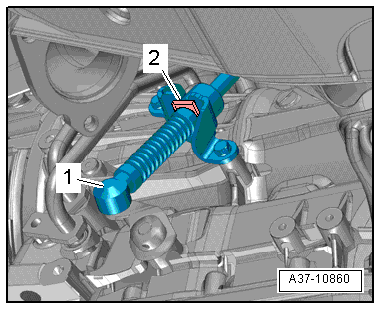
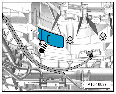
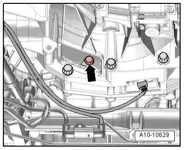
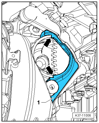
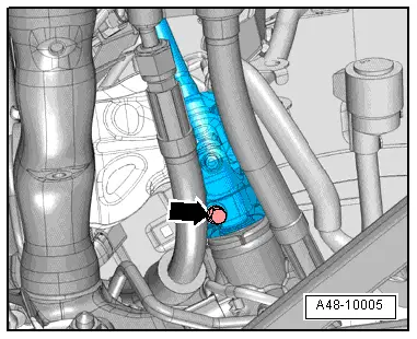
–  Press steering column off steering box and push all the way up.
  A48-10005
–  Remove bolts -arrows- and detach heat shield for propshaft.
  A10-10859
–  Remove securing bolts from connection between propshaft and gearbox (counterhold using counterhold tool -T10172- with -T10172/5-).
–  Slide propshaft together towards rear final drive. The constant velocity joints can be moved axially.
–  Tie propshaft up to one side.
  A39-10185
–  Pull cover -1- off bottom of gearbox -arrow-.
  A10-10628
–  Insert guide stud of adapter -T40058- as follows:
l  The larger diameter -arrow 1- faces engine.
l  The smaller diameter -arrow 2- faces adapter.
  A13-10026
–  To slacken bolts for torque converter, counterhold crankshaft with adapter -T40058-.
  Note
When you then turn the crankshaft, only turn crankshaft in direction of engine rotation -arrow-.
  A13-10022
–  Remove 6 bolts -arrow- for torque converter (turn crankshaft 60° in direction of engine rotation each time).
  A10-10629
–  Remove starter → Electrical system; Rep. Gr.27.
  Note
The starter must be removed so that the end seal -1- can be fitted correctly in the starter aperture when installing the gearbox.
  A37-11006
–  Remove remaining engine/gearbox securing bolts -6 … 11-.
  A34-10370
–  Place used oil collection and extraction unit -V.A.G 1782- below connection.
–  Remove bolts -arrows-, detach hydraulic line -1- from steering box and place to one side.
–  Seal off open lines and connections with clean plugs from engine bung set -VAS 6122-.
  A48-10340
–  Position engine and gearbox jack -V.A.G 1383 A- with gearbox support -T40173- underneath gearbox and secure with tensioning strap -1- as shown in illustration.
  A37-10746
–  Pre-tension spindle -10 - 222 A /11- slightly.
  Note
  A34-10578
For illustration purposes, the gearbox support -T40173- is not shown.
–  Remove bolts -arrows- for tunnel cross member.
  A10-11132
–  Detach gearbox from engine and lower carefully using engine and gearbox jack -V.A.G 1383 A-.
  A37-10746

Installing gearbox - vehicles with 3.0 ltr. TDI engine > < Installing gearbox - vehicles with 4.2 ltr. FSI engine