| l
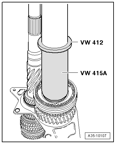
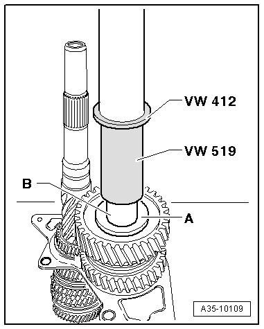
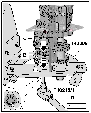
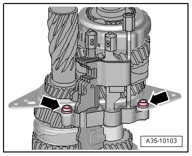
| If you have dismantled and assembled the input shaft, now tighten the multi-point socket head bolt -A- in the input shaft to the specified torque → Item using torque wrench -D-. Before installing the bolt, clean the thread with a wire brush and then apply locking fluid -AMV 185 101 A1-. |
| l
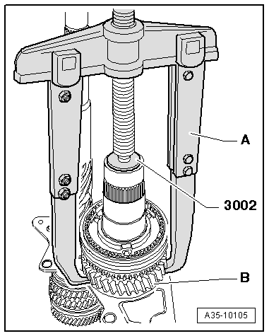
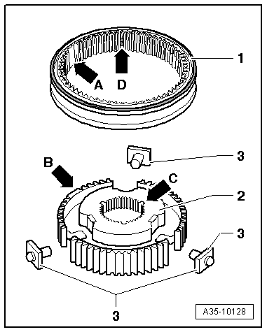
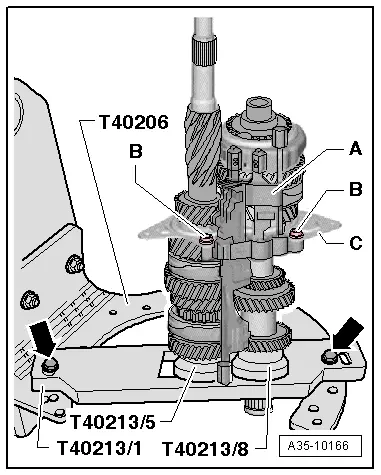
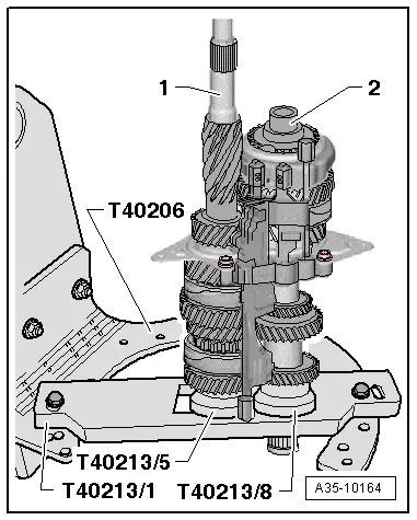
| To do this, engage 2 gears by moving locking collars -B- and -C- in direction of -arrow-. |
| l
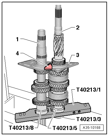
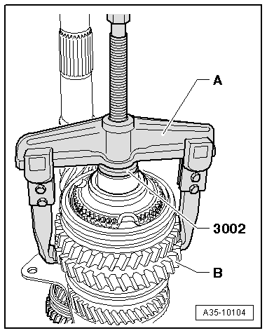
| The shafts must be vertical, as shown in illustration. |
| –
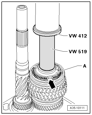
| Then move locking collars back to neutral position. |

Note | In order to move the locking collars -B- and -C- back into the centre position, turn the input shaft slightly anti-clockwise via bolt -A-. |
| –
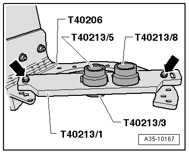
| Remove input shaft together with output shaft and selector fork cluster from plate -T40213/1-. |
|
|
|


 Caution