audi Workshop Repair Guides

Audi Workshop Service and Repair Manuals

Output shaft > < Exploded view - input shaft
Fitting sequence - dismantling and assembling input shaft
   
Fitting sequence - dismantling and assembling input shaft
Special tools and workshop equipment required
t  Thrust plate -VW 401-
t  Thrust plate -VW 402-
t  Press tool -VW 407-
t  Press tool -VW 408 A-
t  Press tool -VW 412-
t  Press tool -VW 454-

   
t  Tube -VW 415 A-
t  Tube -2040-
t  Thrust piece -3118-
t  Tube -3296-
t  Separating tool -T40213-
t  Workshop press -V.A.G 1290A-

   
t  Inductive heater -VAS 6414-
  W00-10814
t  -3-Parting tool 22 ... 115 mm, e.g. -Kukko 17/2-
t  Feeler gauge
Dismantling input shaft
l  Input shaft has been detached from output shaft and bearing mounting → Chapter.
  W00-0633
–  Start by taking out the circlip -A- and the shim -B- behind the ball bearing on the input shaft removed.
  A35-10174
–  Parting tool-A- is to be applied beneath the driver teeth of the 4th speed selector gear and used to press off the ball bearing.
A - Parting tool 22 ... 115 mm, e.g. -Kukko 17/2-
–  Detach the synchro-rings and needle bearing for the 4th speed selector gear.
  A35-10175
–  Parting tool-A- is to be applied beneath the driver teeth of the 6th speed selector gear and used to press off the 3rd/4th gear synchronising hub together with the inner races/needle bearing for the 3rd and 4th speed selector gears.
A - Parting tool 22 ... 115 mm, e.g. -Kukko 17/2-
–  Detach the synchro-rings and needle bearing for the 6th speed selector gear.
  A35-10176
–  Press off the 5th speed selector gear together with the 5th/6th gear synchronising hub and the inner race/needle bearing for the 6th speed selector gear.
  A35-10177
–  Press roller bearing off input shaft.
A - Parting tool 22 ... 115 mm, e.g. -Kukko 17/2-
  Note
t  Apply the parting tool-A- beneath the bearing cage -B-.
t  Position the bearing mounting -C- over the roller bearing on the input shaft to stop the rollers being pressed out of the bearing cage -B-.
t  For pressing off, it is also possible to destroy the cage of the roller bearing with a screwdriver for example and then apply the parting tool-A- to the inner race.
Assembling input shaft
  Note
t  Lubricate all needle bearings and synchro-rings with gear oil before fitting.
t  Before pressing on, heat the needle bearing inner races to max. 100 °C (wear protective gloves when doing so).
t  Heat synchronising hubs to 100 °C (max.) before pressing on (wear protective gloves).
t  Always press on roller bearing, needle bearing inner races and synchronising hubs as far as stop to make sure the axial clearance of the selector gears meets the specification.
  A35-10178
Checking synchro-rings for 3rd to 6th gear for wear
–  Check the outer friction surface of the inner ring for scoring or visible signs of wear and replace if necessary.
–  Check the inner friction surface of the synchro-ring for scoring or visible signs of wear and replace if necessary.
–  Fit and “seat” the inner ring, intermediate ring and synchro-ring on the taper of the selector gear.
  Note
“Seating” means: Give the synchro-rings roughly one turn whilst at the same time pressing them on.
–  Then measure gap -a- using a feeler gauge.
  A35-0087
Gap -a-Wear limit
3rd to 6th gear0.7 mm

  Note
Jointly replace the inner ring, intermediate ring and synchro-ring for the corresponding gear.
   
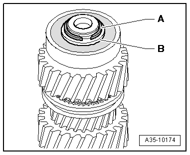
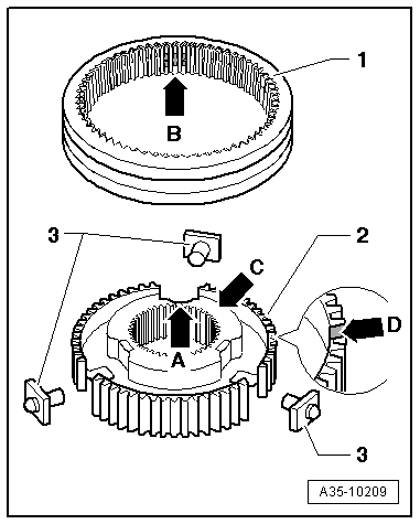
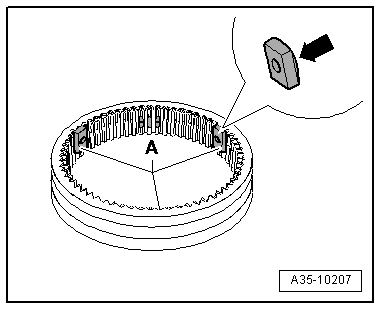
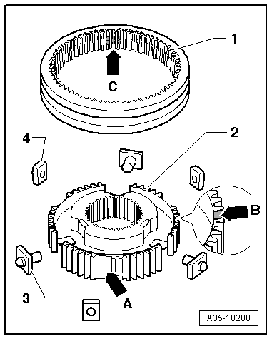
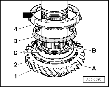
Installation position of synchro-rings for 3rd to 6th gear
  Note
If components are not being renewed, make sure they are re-installed on the same gear.
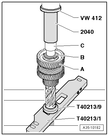
–  Fit the inner ring -2- on the selector gear -1-.
–  Fit the intermediate ring -3-. The lug -B- must be inserted in the recess -A-.
–  Fit the synchro-ring -4-. Guide the lugs -C- through the recess -arrow-.
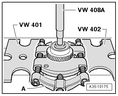
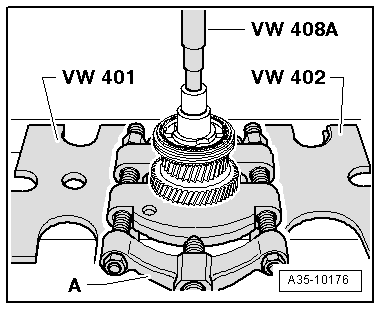
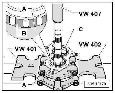
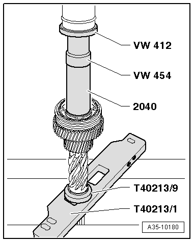
Note the following when performing the following steps:
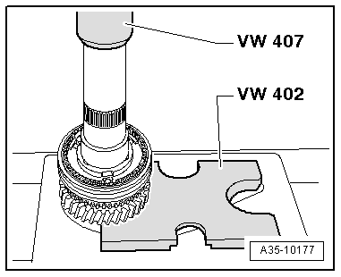
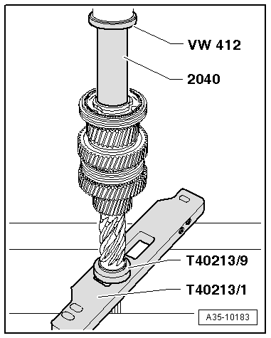
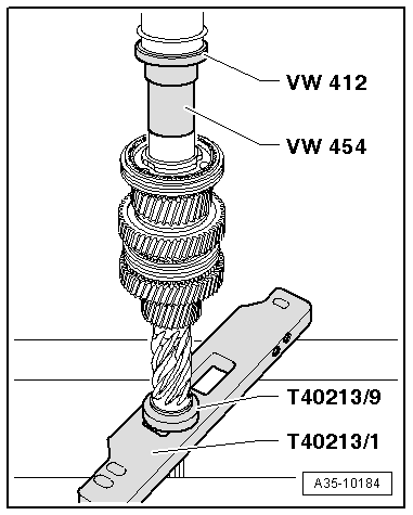
–  Position drift sleeves on centre of heated components (synchronising hub and needle bearing inner races).
–  First press on components just briefly, then stop exerting pressure and check whether drift sleeves are still positioned properly and press on as far as stop.
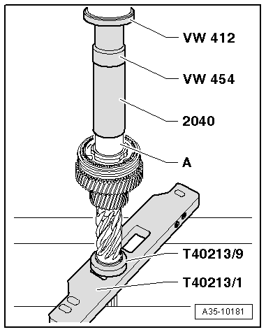
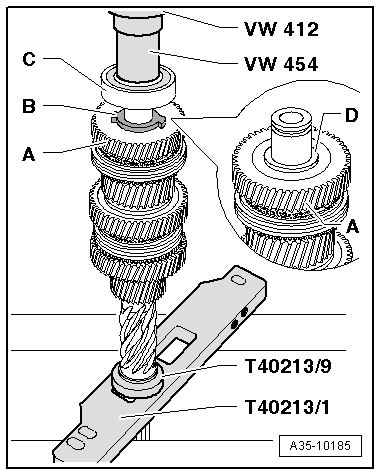
When pressing on, the lugs of the synchro-ring and the recesses of the synchronising hub must coincide. To do so, lift the corresponding selector gear with synchro-rings slightly to lock it in the recesses of the synchronising hub.
  A35-0093
–  Position the plate -T40213/1- with the adapter -T40213/9- on the table of the workshop press -V.A.G 1290A-.
–  Position the input shaft in the adapter -T40213/9-.
–  Press roller bearing onto input shaft as far as stop.
–  Fit the 5th speed selector gear together with the needle bearing and synchro-rings.
  A35-10179
Assembling locking collar/synchronising hub for 5th and 6th gear
–  Slide the locking collar -1- over the synchronising hub -2-.
l  The recesses -arrow A- for the thrust pieces -3- in the synchronising hub and the recesses -arrow B- in the locking collar must coincide.
l  Installation position: High collar on inside -arrow C- or notch -arrow D- of synchronising hub must face 5th speed selector gear.
–  Then insert the thrust pieces -3- in the synchronising hub and press the thrust pieces into the recesses -arrow B- of the locking collar.
  A35-10209
Pressing on 5th and 6th gear synchronising hub with locking collar
  A35-10180
Pressing on inner race/needle bearing -A- for 6th speed selector gear
  A35-10181
–  Fit the 6th speed selector gear -A- together with the needle bearing and synchro-rings.
–  Position the thrust washer -B- on the 6th speed selector gear.
–  Press on the inner race/needle bearing -C- for the 3rd speed selector gear.
–  Fit the 3rd speed selector gear together with the needle bearing and synchro-rings.
  A35-10182
Inserting locking pieces -A- in locking collar
–  Coat the 3 locking pieces -A- with a small quantity of grease on the curved side -arrow-.
–  Insert the curved side of the 3 locking pieces in the locking collar recesses.
  A35-10207
Assembling locking collar/synchronising hub for 3rd and 4th gear
l  Insert the 3 locking pieces -4- in installation position in the locking collar recesses -1- → Fig..
l  Installation position of synchronising hub: Notch -arrow B- or “labelling” must face 4th speed selector gear.
–  Position the locking collar -1- over the synchronising hub -2- such that the recesses of the synchronising hub -arrow A- coincide with the locking pieces inserted in the locking collar.
–  Then insert the thrust pieces -3- in the synchronising hub and press the thrust pieces into the recesses -arrow C- of the locking collar.
  A35-10208
Pressing on 3rd and 4th gear synchronising hub with locking collar
  A35-10183
Pressing on inner race/needle bearing for 4th speed selector gear
  A35-10184
–  Fit the 4th speed selector gear -A- together with the needle bearing and synchro-rings.
–  Fit the thrust washer -B-.
l  Check that the inner race/needle bearing -D- for the 4th speed selector gear is higher than the 4th speed selector gear -A-.
–  Press home the ball bearing -C-.
–  Then check all selector gears for freedom of movement and axial play.
l  The axial play of the selector gears must be at least 0.15 mm.
  A35-10185
Determine the thickness of the shim -B- as follows:
–  Select the thickest shim which can still just be inserted from the shims -B- available as replacement parts → Electronic parts catalogue.
l  The circlip -A- must be in contact with the bottom of the groove when determining the shim.
  A35-10174

Output shaft > < Exploded view - input shaft