
A4 Mk3
| Diagram of coolant hose connections |
 Note
Note| t | Blue = Large coolant circuit. |
| t | Red = Small coolant circuit. |
| t | Brown = Heating circuit. |
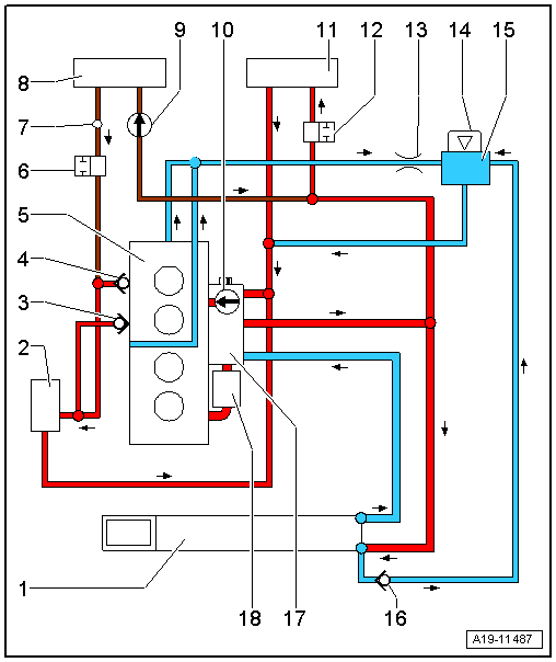
| 1 - | Radiator |
| q | If renewed, refill system with fresh coolant |
| 2 - | Turbocharger |
| 3 - | Non-return valve |
| 4 - | Non-return valve |
| 5 - | Cylinder head/cylinder block |
| q | If renewed, refill system with fresh coolant |
| 6 - | Coolant shut-off valve |
| q | Activated by Climatronic coolant shut-off valve -N422- (negative pressure) |
| q | Removing and installing → Rep. gr.87 |
| 7 - | Bleeder hole |
| 8 - | Heat exchanger for heater |
| q | Removing and installing → Rep. gr.87 |
| q | If renewed, refill system with fresh coolant |
| 9 - | Coolant circulation pump -V50- |
| q | Only installed on vehicles with start/stop system |
| 10 - | Coolant pump |
| q | Removing and installing → Chapter |
| 11 - | Gear oil cooler |
| 12 - | Coolant shut-off valve |
| 13 - | Restrictor |
| 14 - | Filler cap for expansion tank |
| q | Checking pressure relief valve → Anchor |
| 15 - | Coolant expansion tank |
| 16 - | Non-return valve |
| 17 - | Actuator for engine temperature regulation -N493- |
| q | Removing and installing → Chapter |
| 18 - | Engine oil cooler |