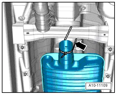
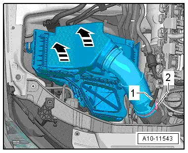
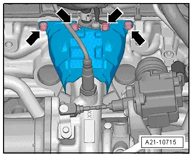
| –
| Pull turbocharger off studs in direction of -arrow-. |
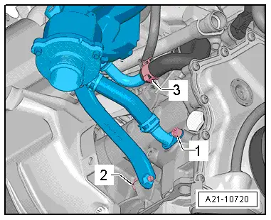
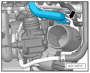
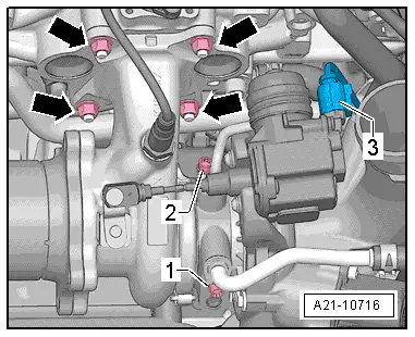
| –
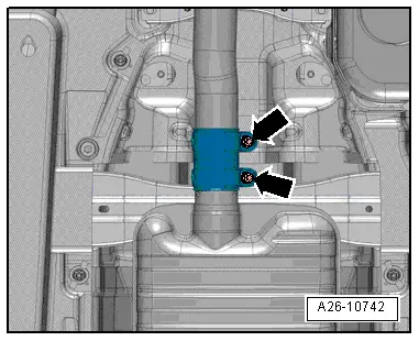
| Have a second mechanic hold turbocharger; remove bolt -1-, disconnect coolant supply line -2- and lift out turbocharger. |
| Installation is carried out in the reverse order; note the following: |

Note | t
| Renew seals, gaskets, O-rings and self-locking nuts. |
| t
| Fill turbocharger with engine oil at connection for oil supply line. |
| t
| Hose connections and hoses for charge air system must be free of oil and grease before assembly. |
| –
| Align the exhaust system so it is free of stress → Chapter. |
| –
| Install air pipes/hoses with plug-in connectors → Chapter. |
Note | After installing turbocharger, allow engine to idle for approx. 1 minute and do not rev up immediately to ensure turbocharger is supplied with oil. |
|
|
|

 WARNING
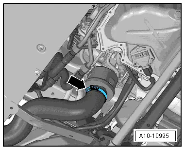
 Caution