audi Workshop Repair Guides

Audi Workshop Service and Repair Manuals

Supporting engine with support bracket > < Securing engine to assembly stand
Installing engine
Installing engine
Special tools and workshop equipment required
   
t  Counterhold tool -T10355- for vehicles with dual clutch gearbox
  W00-10474
t  Assembly aid -T40169-
  W00-10593
t  Transport lock -T40170-
Tightening torques
  Note
t  Tightening torques apply only to lightly greased, oiled, phosphated or black-finished nuts and bolts.
t  Additional lubricants such as engine or gear oil may be used, but do not use lubricants containing graphite.
t  Do not use degreased parts.
t  Tolerance for tightening torques: ± 15 %.
Tightening torques → Chapter „Assembly mountings - exploded view“
Further tightening torques
  W00-10594
ComponentNm
Bolts/nutsM69
M820
M1040
M1265

   
Securing engine to manual gearbox
  A34-10491
ItemBoltNm
1 3)M10 x 50 1)65
2 3), 7M12 x 100 2)30 + 90°
3 4), 6M12 x 75 2)30 + 90°
4 ... 5 4)M12 x 120 2)30 + 90°
8 ... 10M10 x 75 2)15 + 90°
11M12 x 50 2)30 + 90°
ADowel sleeves for centralising
l  1) Steel bolt - is not renewed
l  2) Renew bolts
l  3) Also secures starter
l  4) Also secures cable retainer

Procedure
  Note
t  Renew the bolts tightened with specified tightening angle.
t  Renew self-locking nuts and bolts as well as seals, gaskets and O-rings.
t  Hose connections and hoses for charge air system must be free of oil and grease before assembly.
t  Secure all hose connections with the correct type of hose clips (same as original equipment) → Electronic parts catalogue.
t  To secure the charge air hoses at their connections, spray rust remover onto the worm thread of the used hose clips before installing.
t  Fit all cable ties in the original positions when installing.
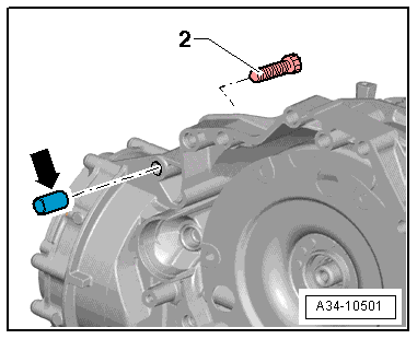
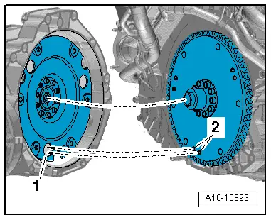
–  Check that dowel sleeves for centring engine and gearbox are fitted in the cylinder block; install missing dowel sleeves.
–  Before installing gearbox, remove residue from threaded holes for engine/gearbox bolts in cylinder block using a thread tap.
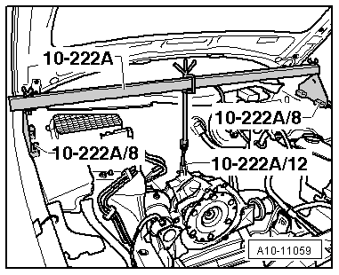
–  The following preparations are required before joining engine and gearbox.
   
–  Ensure that intermediate plate is engaged on sealing flange and pushed onto dowel sleeves -arrows-.
  A10-0129
–  Insert assembly aid -T40169- into gearbox housing and clutch module from below, as illustrated.
l  The assembly aid -T40169- must engage in the semi-circular recess -1- and in the inspection hole -2-.
  Note
There is only one inspection hole on the circumference; turn the clutch module accordingly.
  A10-10825
–  Insert retainer -T40170- into gearbox housing from below and clamp onto flange shaft -1-.
  Note
  A10-10826
The next work step is only required if a drive plate with locating pins -2- is fitted.
–  In addition, align drive plate relative to clutch module so that locating pins -2- (if fitted) on drive plate are in position to engage in large holes -1- in clutch module.
  Caution
Incorrect installation will cause the clutch mechanism to malfunction.
If the locating pins of the drive plate -2- do not engage in the holes in the clutch module -1-, this can cause serious malfunctioning of the clutch mechanism.
  Note
t  Bolt -2- secures the starter to the gearbox and is provided with a spacer sleeve -arrow-.
  A10-10893
t  Pay attention to the spacer sleeve -arrow- when removing and installing the engine. The spacer sleeve must be fitted between starter and gearbox.
  A34-10501
–  Bring gearbox into position on engine and tighten bolts -7 … 11- securing engine to gearbox. Tightening torques → Anchor
  A34-10491
–  Release spindle of support bracket -10-222 A-.
–  Lower workshop hoist and place engine/gearbox assembly onto engine mounting.
  A10-11059
–  Fit bolts -1- for left and right engine mountings.
–  Detach workshop hoist -VAS 6100- and lifting tackle -2024 A-.
  A40-10226
–  Screw in bolts -1 ... 6- of engine/gearbox assembly and tighten.
  Note
Disregard -item A-.
  A34-10491
–  Remove retainer -T40170- and assembly aid -T40169-.
  Note
The following step is necessary to ensure that the clutch module is straight and that it makes even contact with the drive plate.
–  Use assembly lever -1- to press clutch module -2- slightly against drive plate -3- in direction of -arrow-.
  A34-10497
Tightening sequence - clutch module to drive plate
–  Screw in first bolt -arrow- hand-tight.
–  Turn crankshaft by 120° in direction of engine rotation and fit second bolt hand-tight.
–  Turn crankshaft by 120° in direction of engine rotation once again.
–  Then tighten third bolt to final torque → Rep. gr.30.
–  Then tighten remaining bolts to final torque.
The remaining installation steps are carried out in the reverse sequence.
–  Install starter → Rep. gr.27
–  Install catalytic converter → Chapter.
–  Install front exhaust pipe/front silencer → Chapter.
–  Align the exhaust system so it is free of stress → Chapter.
–  Install air conditioner compressor → Rep. gr.87.
–  Install poly V-belt → Chapter.
–  Electrical connections and routing → Current flow diagrams, Electrical fault finding and Fitting locations.
–  Install engine control unit → Rep. gr.23.
–  Install electrical wiring, terminal 30 wiring junction 2 -TV22- and cover for electronics box in engine compartment → Rep. gr.97.
–  Install body brace → Rep. gr.40.
–  Install filler neck for washer fluid reservoir → Rep. gr.92.
–  Observe notes on procedure for connecting the battery → Rep. gr.27.
  Caution
Risk of irreparable damage to control units because of excessive voltage.
Never use battery charging equipment for boost starting.
–  Install air cleaner housing → Rep. gr.23.
–  Reset service position → Rep. gr.50.
Check oil level; A4 → Booklet812, A5 → Booklet811
–  Fill up with coolant → Anchor.
  Note
t  Do not use drained coolant again if:
t  the cylinder head or cylinder block have been renewed.
t  the coolant is contaminated or dirty.
–  Install noise insulation and wheel housing liners → Rep. gr.66.
  A10-10629

Supporting engine with support bracket > < Securing engine to assembly stand