
A4 Mk3
| Removing engine |
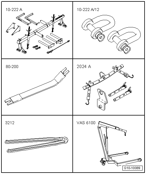
| Special tools and workshop equipment required |
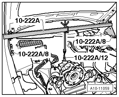
| t | Support bracket -10 - 222 A- |
| t | Shackle -10 - 222 A /12- |
| t | Removal lever -80 - 200- |
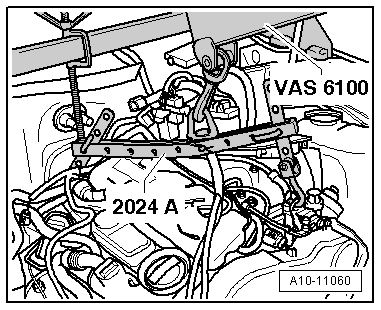
| t | Lifting tackle -2024 A- |
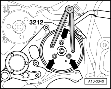
| t | Pin wrench -3212- |
| t | Workshop hoist -VAS 6100- |
|
|
|
|
|
|
 Note
Note
|
|
|
|
 Caution
|
|
|
|
 WARNING
Note |
|
|
|
|
|
|
|
|
|
Note
|
|
|
|
|
|
|
|
Note
|
|
|
|
Note
|
|
|
|
Note
|
|
|
|
|
|
Note
|
|
|
|
|
|
|
|
|
|
|
|
Note
|
|
|
|
|
|
|
|
|
|
|
|
|
|
|
|
|
|
|
|
|
|
|
|
|
|
|
|
|
|
Note
|
|
Note
|
|
|
|
|
|
|
|
Note
|
|
|
|
Note
|
|
Note
|
|
|
|
Note
Note |
|
|
|
Note
|
|
|
|
Note |
|
|
|