audi Workshop Repair Guides

Audi Workshop Service and Repair Manuals

Separating engine from multitronic gearbox 0AW > < Removing engine - vehicles with multitronic gearbox 0AW
Removing engine
   
Removing engine
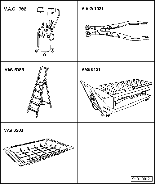
Special tools and workshop equipment required
t  Used oil collection and extraction unit -V.A.G 1782-
t  Hose clip pliers -V.A.G 1921-
t  Stepladder -VAS 5085-
t  Scissor-type assembly platform -VAS 6131 A- with support set for Audi -VAS 6131/10-, support set -VAS 6131/11- and supplementary set -VAS 6131/13-
t  Drip tray for workshop hoist -VAS 6208-

   
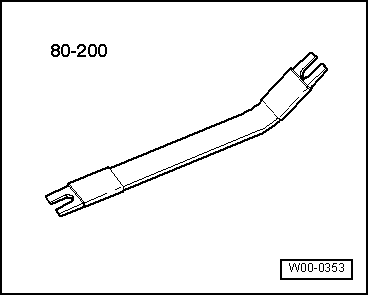
t  Removal lever -80 - 200-
  W00-0353
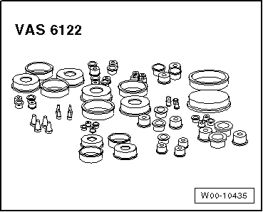
t  Engine bung set -VAS 6122-
Procedure
  WARNING
Make sure the vehicle cannot tip over when the engine is removed.
Secure the vehicle, to do so, the luggage compartment must be empty.
The fuel system operates at extremely high pressure. This can cause injury.
The fuel pressure in the high-pressure section of the injection system must be reduced to a residual pressure prior to opening the system.
–  Reduce fuel pressure in high-pressure section of injection system → Chapter.
–  Set front wheels to straight-ahead position.
  W00-10435
  Caution
Electronic components are susceptible to damage.
Observe notes on procedure for disconnecting the battery.
–  Switch off ignition and take out ignition key.
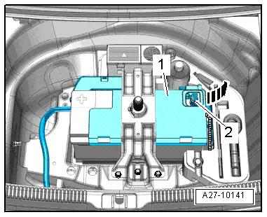
–  Disconnect earth wire -2- from battery terminal → Rep. Gr.27.
–  Discharge refrigerant system → Air conditioner with refrigerant R134a.
–  Extract hydraulic fluid for power steering from reservoir using used oil collection and extraction unit -V.A.G 1782-.
  A27-10141
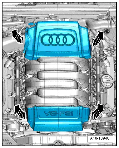
–  Pull off engine cover panels -arrows-.
  WARNING
Hot steam/hot coolant can escape - risk of scalding.
t  The cooling system is under pressure when the engine is hot.
t  To allow pressure to dissipate, cover filler cap on expansion tank with cloth and open carefully.
–  Open filler cap on coolant expansion tank.
  A10-10940
–  Remove both front wheels.
–  Remove front left and front right wheel housing liners → Rep. Gr.66.
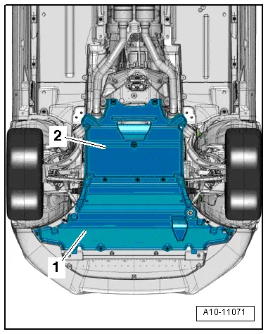
–  Remove noise insulation panels -1- and -2- → Rep. Gr.66.
  A10-11071
–  Place drip tray for workshop hoist -VAS 6208- beneath engine.
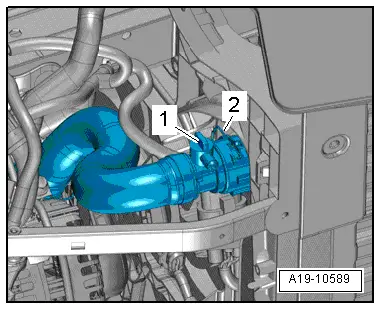
–  Remove drain plug -1- and drain off coolant.
–  Lift retaining clip -2- and disconnect coolant hose from radiator.
  A19-10589
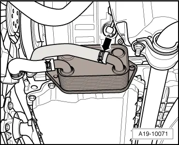
–  Disconnect coolant hose -arrow- from oil cooler and drain off remaining coolant.
  A19-10071
–  Position used oil collection and extraction unit -V.A.G 1782- below connection point.
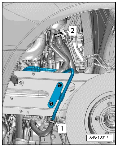
–  Disconnect supply hose -2- and return hose -1- for power steering hydraulic fluid in front left wheel housing and move clear.
–  Seal off open pipes/lines and connections with clean plugs from engine bung set -VAS 6122-.
  A48-10317
–  Position used oil collection and extraction unit -V.A.G 1782- below connection point.
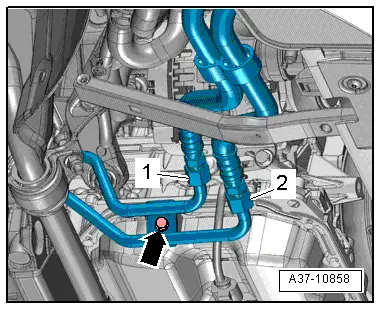
–  Mark position of ATF lines -1- and -2- for re-installation and disconnect ATF lines.
–  Seal off open pipes/lines and connections with clean plugs from engine bung set -VAS 6122-.
  Note
Disregard -arrow-.
  A37-10858
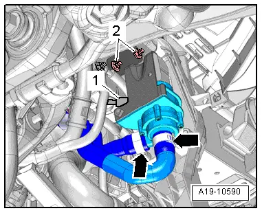
Vehicles with coolant circulation pump -V50-:
–  Unplug electrical connector -1-.
–  Place drip tray for workshop hoist -VAS 6208- beneath engine.
–  Disconnect coolant hose from continued coolant circulation pump -V50--right arrow-.
  Note
Disregard -item 2- and -left arrow-.
  A19-10590
All vehicles (continued):
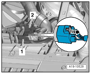
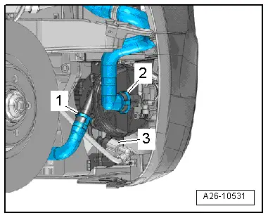
–  Unplug electrical connectors -1- and, if fitted, -2- for radiator fan (push retainer to the rear -arrow- and press down release catch).
–  Move electrical wiring clear.
  A19-10529
–  If fitted, detach electrical connector -3- at secondary air pump motor -V101- and move electrical wire clear.
  Note
Disregard -items 1, 2-.
  A26-10531
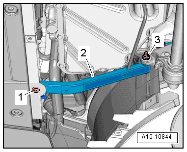
–  Remove bolt -1- and nut -3- on both sides and detach strut -2- for lock carrier.
  A10-10844
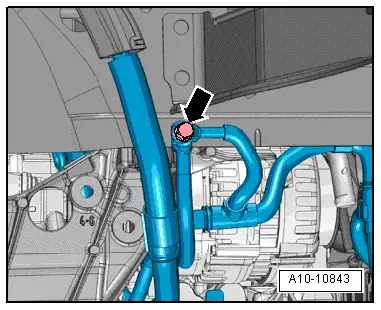
–  Unscrew nut -arrow- on longitudinal member (right-side) and move earth cables clear.
  A10-10843
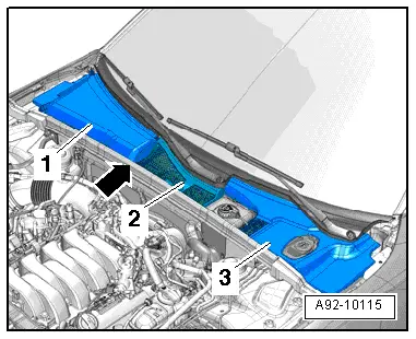
–  Remove seal -arrow-.
–  Remove plenum chamber cover → Rep. Gr.50.
  A92-10115
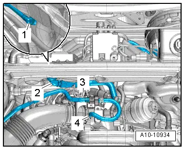
–  Disconnect vacuum hose -1- on rear side of bulkhead and detach vacuum connection -2- from bulkhead.
–  Move fuel line and line leading to activated charcoal filter clear at air pipe.
–  Unplug electrical connector -3- at activated charcoal filter solenoid valve 1 -N80- and detach vacuum hose -4-.
–  Detach activated charcoal filter solenoid valve 1 -N80- from bracket and move it clear to the side with hoses still attached.
  A10-10934
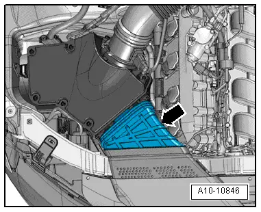
–  Remove air duct -arrow-.
  A10-10846
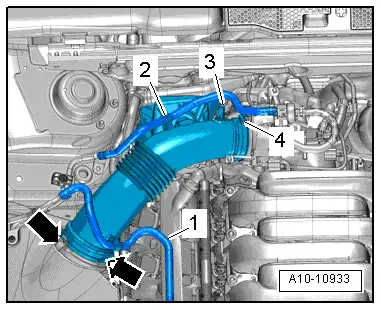
–  Move fuel hose -1- clear at air pipe.
–  Disconnect vacuum hose -3- from connection on air pipe.
–  Remove air pipe. To do so, release hose clip -4- and clamps -arrows-.
  Note
Disregard -item 2-.
  A10-10933
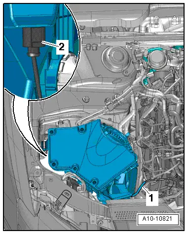
–  Disconnect vacuum line -1-.
–  Detach air cleaner housing and, if fitted, unplug electrical connector -2- at variable intake manifold change-over valve -N335- on reverse side of air cleaner.
  A10-10821
  WARNING
Risk of injury caused by fuel.
To allow the fuel pressure to dissipate, wrap a clean cloth around the connection and carefully loosen the connection before opening the fuel system.
  Caution
Take care to keep components clean.
Observe rules for cleanliness when working on the fuel supply system → Chapter.
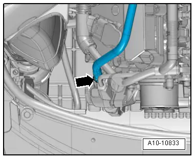
–  Disconnect fuel supply hose from high-pressure pump -arrow- and move clear to one side.
–  Seal off open pipes/lines and connections with clean plugs from engine bung set -VAS 6122-.
  A10-10833
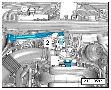
–  If fitted, disconnect vacuum hose -1- and move clear.
–  Lift retaining clip and detach coolant hose -2- from coolant pipe (top).
  A19-10592
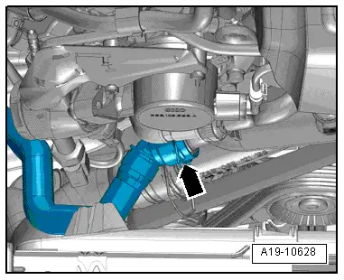
–  On vehicles without coolant circulation pump -V50- and with auxiliary heater, lift retaining clip -arrow- and detach coolant hose at front right of coolant pipe (front).
  A19-10628
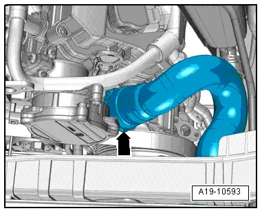
–  Lift retaining clip -arrow- and detach coolant hose from coolant pipe (front).
  A19-10593
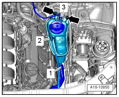
–  Disconnect coolant hose -3- from coolant expansion tank and move clear.
–  Remove bolts -arrows-, unplug electrical connector at coolant shortage indicator switch -F66- and move expansion tank to one side with coolant hoses -1- and -2- attached.
  A10-10850
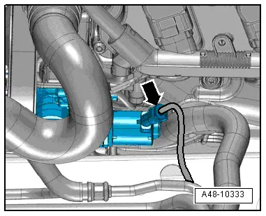
–  If fitted, unplug electrical connector -arrow- at power steering pump.
–  Press hydraulic fluid hose down slightly.
  A48-10333
  Caution
Danger of damage to refrigerant lines and hoses.
Do NOT stretch, kink or bend refrigerant lines and hoses.
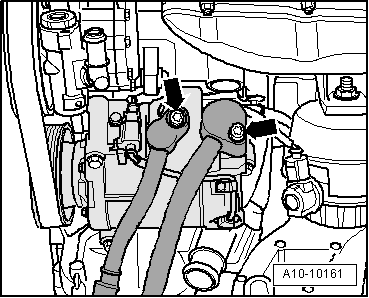
–  Remove bolts -arrows- and disconnect refrigerant lines from A/C compressor.
–  Seal off open pipes/lines and connections with clean plugs from engine bung set -VAS 6122-.
  A10-10161
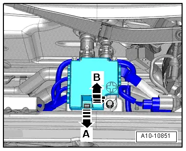
–  Release retainer -arrow A- and open cover -arrow B-.
  A10-10851
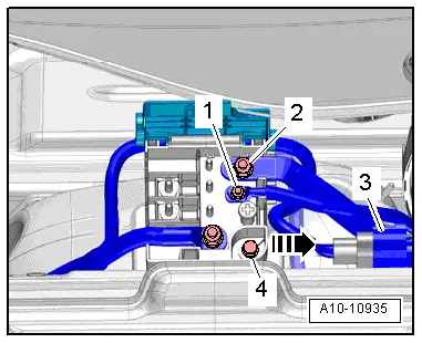
–  Remove nuts -1- and -2- for electrical wiring.
–  Detach electrical connector -3- from bracket and unplug.
–  Remove bolt -4- and detach terminal 30 wiring junction 2 -TV22- from body brace -arrow-.
  A10-10935
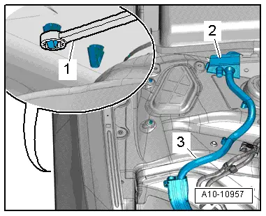
–  Working from wheel housing, release catches using a 5.5 mm ring spanner -item 1- and remove wiring protector -2- from above.
–  Release wiring harness -3- leading to alternator and starter using removal lever -80 - 200- and move clear.
  A10-10957
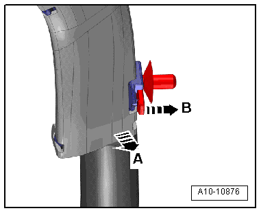
–  Wiring duct (version 1): release catch -arrow B- and move wiring duct clear by pulling it towards front -arrow A-.
  A10-10876
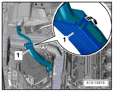
–  Wiring duct (version 2): release catch -arrow- to open wiring duct -1- and move wiring harness clear.
  A10-10816
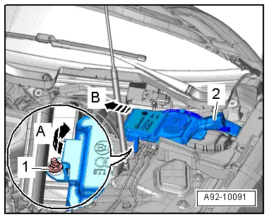
–  Remove nut -1- and swivel filler neck -2- for washer fluid reservoir slightly upwards -arrow A-.
–  Pull filler neck with filler pipe out of washer fluid reservoir and through opening in body -arrow B-.
  A92-10091
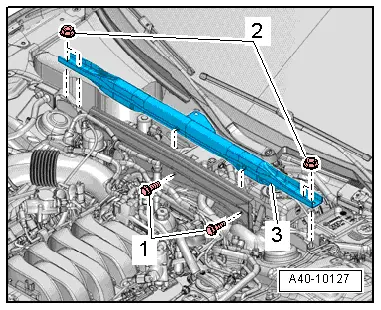
–  Remove bolts -1- and nuts -2- and detach body brace -3-.
  A40-10127
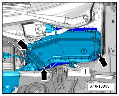
–  Remove bolts -arrows- and detach cover for electronics box in engine compartment.
–  Remove nut -1- and move electrical wiring clear.
  A10-10853
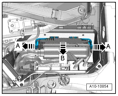
–  Release catches -arrows A- and take out engine control unit -arrow B-.
  A10-10854
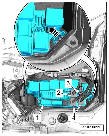
–  If fitted, unplug electrical connector -2-.
–  Unplug electrical connectors -4- and unscrew nut -3- for wiring.
–  Release catches -arrow- and detach relay carrier with fuse holder -1-.
–  Disengage engine wiring harness at electronics box in engine compartment and move clear.
  A10-10855
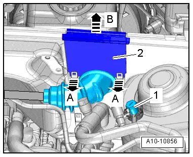
–  Release catches -arrows A- and lift off wiring protector -2--arrow B-.
–  Unscrew earth stud -1- and move wiring harness clear.
–  Place wiring harness on engine and secure engine control unit to prevent it from dropping.
  A10-10856
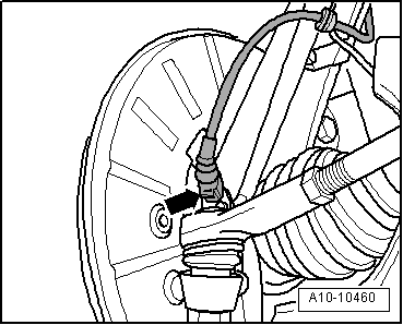
–  Unplug electrical connectors -arrow- at front wheel speed sensors on both sides.
  A10-10460
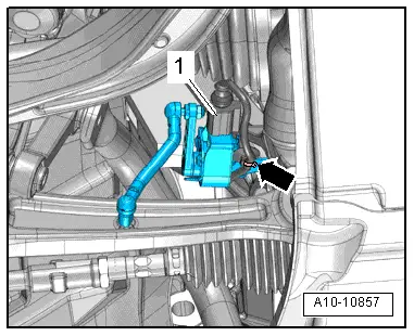
–  Unplug electrical connector -1- from front left vehicle level sender -G78- and front right vehicle level sender -G289- and move wiring clear -arrow-.
  A10-10857
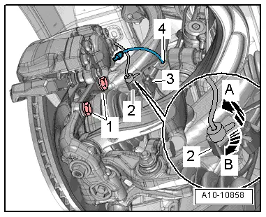
–  Release electrical connector -2- at bracket by pulling retainer catch to the rear -arrow A- and turning connector approx. 90° clockwise -arrow B-.
–  Move clear electrical wire -3- and brake hose -4- at bracket.
–  Remove bolts -1- and tie up brake caliper in wheel housing with wire.
  Caution
Avoid damage to brake pistons.
Do not operate brake pedal with brake caliper removed.
  A10-10858
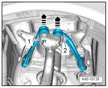
–  Remove nut -2- and pull out bolt -1-.
–  Pull upper suspension links upwards out of wheel bearing housing -arrows-.
–  Perform the same work steps on the other side of the vehicle.
  A40-10128
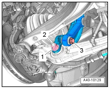
A5 up to vehicle identification no. 8T-8-011200:
–  Remove bolt -3- for anti-roll bar on both sides.
–  Remove nut -1- on both sides.
  Note
The bolts -2- are removed at a later stage.
  A40-10129
A4 (all), A5 from vehicle identification no. 8T-8-011201 onwards:
–  Remove bolt -1- for anti-roll bar on both sides.
–  Remove nut -3- on both sides.
  Note
The bolts -2- are removed at a later stage.
All vehicles (continued):
  Caution
Risk of damage to running gear components.
The vehicle must NOT be lowered onto its wheels if the engine/gearbox mountings, steering box or subframe cross brace are not properly installed.
  A40-10132
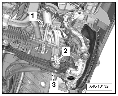
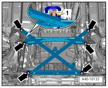
A4 (all), A5 Coupé:
–  Remove nut -1- for power steering hydraulic line.
–  Remove bolts -arrows- and detach subframe cross brace.
  Note
Illustration shows the installation position on a vehicle with dynamic steering.
  A40-10133
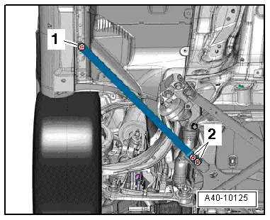
A5 Cabriolet:
–  Remove bolts -1- and -2- on both sides and detach strut.
  A40-10125
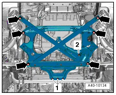
–  Remove bolt -2- for power steering hydraulic line.
–  Remove bolts -1- and -arrows- and detach subframe cross brace.
  A40-10134
All vehicles (continued):
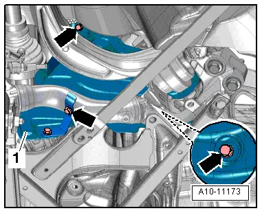
–  If fitted, remove bolts -arrows- on both sides and detach heat shield -1-.
  A10-11173
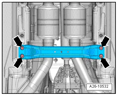
–  If fitted, remove bolts -arrows- and detach front cross member.
  A26-10532
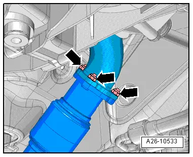
–  Unscrew nuts -arrows- for front silencer (left-side).
  A26-10533
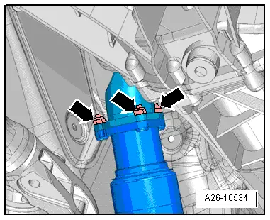
–  Unscrew nuts -arrows- for front silencer (right-side).
  A26-10534
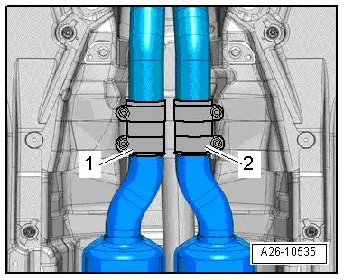
  Caution
Risk of damage to flexible joints in front silencer.
Do NOT bend the flexible joints in the front silencer more than 10°.
–  Loosen and push back clamps -1- and -2- and detach front silencers on both sides.
  A26-10535
  Caution
Risk of damage to coil connector for airbag.
t  Make sure that front wheels are in straight-ahead position before removing universal joint from steering box.
t  Do not alter position of steering wheel and steering box (locate steering wheel with adhesive tape if necessary).
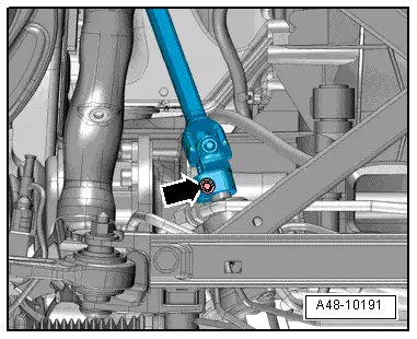
–  Remove bolt -arrow- for universal joint → Rep. Gr.48.
–  Separate universal joint from steering box and move clear to the top as far as possible.
  A48-10191
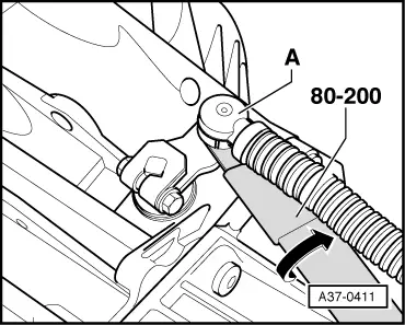
–  Pry ball socket -A- of selector lever cable off selector shaft lever in direction of -arrow- using removal lever -80 - 200-.
  A37-0411
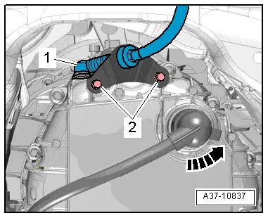
–  Remove bolts -2- for support bracket.
  Note
t  Take care not to bend or kink selector lever cable.
t  Disregard items marked -1- and -arrow-.
  A37-10837
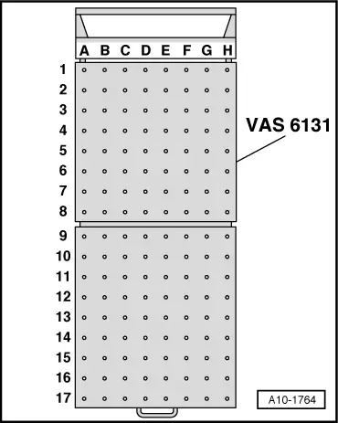
Set up the scissor-type assembly platform as follows:
–  Set up scissor-type assembly platform -VAS 6131 A- with support set for Audi -VAS 6131/10- and supplementary set -VAS 6131/13- as follows:
  A10-1764
Platform coordinatesParts of support set for Audi -VAS 6131/10- and supplementary set -VAS 6131/13-
B4/13-4/10-4/10-5/13-1
G4/13-4/10-4/10-5/13-1
B6/10-1/10-2/10-5/10-11
G6/10-1/10-2/10-5/10-11
A8+C8/13-6/13-2
F8+H8/13-6/13-2
C13/10-1/10-4/10-5/10-13
F13/10-1/10-4/10-5/10-10

–  Initially hand-tighten the support elements on the scissor-type assembly platform.
–  Position scissor-type assembly platform -VAS 6131 A- horizontally.
l  Take note of spirit level (bubble gauge).
–  Position scissor-type assembly platform -VAS 6131 A- below engine/gearbox assembly.
   
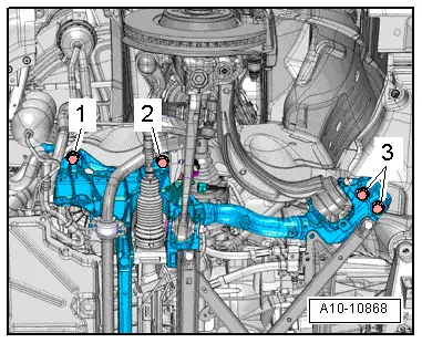
  WARNING
Accident risk if subframe mountings are detached.
Subframe bolts -2- and -3- must not be loosened.
–  Remove subframe bolts -1- on both sides.
  A10-10868
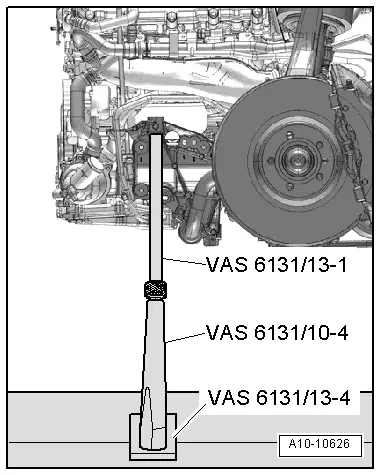
–  Position support elements from -VAS 6131/10- and -VAS 6131/13- at front left and right of subframe as shown.
–  Make sure that threaded spindles are screwed in completely.
  A10-10626
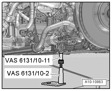
–  Position support elements from -VAS 6131/10- (rear left and right) at front attachment points of subframe cross brace as shown.
  A10-10863
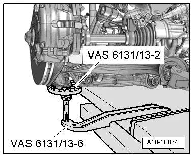
–  Position support elements from -VAS 6131/13- under left and right wheel bearing housings as shown.
  A10-10864
–  Detach retaining clips for noise insulation from cross member.
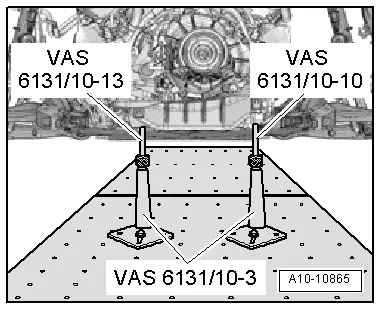
–  Position support elements from -VAS 6131/10- at rear of cross member on both sides, as shown in illustration.
–  Turn all spindles for support elements upwards until all locating lugs make contact with mounting points.
–  Tighten base plates for support elements to 20 Nm on scissor-type assembly platform -VAS 6131 A-.
  A10-10865
–  Mark installation position of subframe and tunnel cross member on longitudinal members with felt-tip pen.
–  Unscrew subframe bolts -2- and -3- on both sides in several stages and in diagonal sequence.
  Note
Disregard -item 1-.
  A10-10868
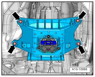
–  Remove bolts -arrows- on tunnel cross member.
  A10-10866
A5 up to vehicle identification no. 8T-8-011200:
–  Remove bolt -2- on both sides.
  A40-10129
A4 (all), A5 from vehicle identification no. 8T-8-011201 onwards:
–  Remove bolt -2- on both sides.
All vehicles (continued):
  Caution
Danger of damage to hoses, pipes and wiring connections and to engine compartment.
t  Check that all hoses and wiring connections between engine, gearbox, subframe and body have been detached.
t  Carefully guide engine/gearbox assembly with subframe out of engine compartment when lowering.
–  Lower engine/gearbox assembly using scissor-type assembly platform -VAS 6131 A-.
–  Pull out scissor-type assembly platform -VAS 6131 A- with engine/gearbox assembly from beneath vehicle.
  A40-10132

Separating engine from multitronic gearbox 0AW > < Removing engine - vehicles with multitronic gearbox 0AW