
A4 Mk3
| Valve gear - exploded view |
 Note
Note| The diagram shows the cylinder head on cylinder bank 2 (left-side). |
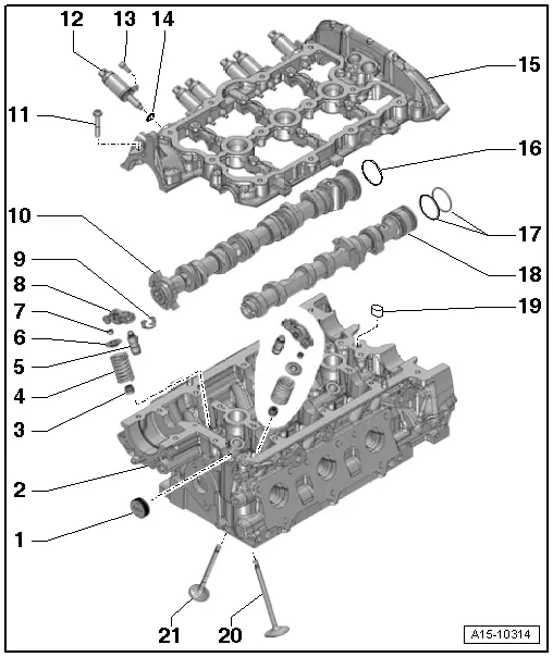
| 1 - | Sealing plug |
| q | Apply sealant when installing; refer to → Electronic parts catalogue |
| 2 - | Cylinder head |
| q | Checking valve guides → Chapter |
| 3 - | Valve stem oil seal |
| q | Renewing with cylinder head installed → Chapter |
| q | Renewing with cylinder head removed → Chapter |
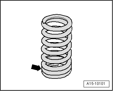
| 4 - | Valve spring |
| q | Installation position → Fig. |
| 5 - | Hydraulic valve compensation element |
| q | Checking → Chapter |
| q | Mark installation position for re-installation with a coloured pen |
| q | Lubricate contact surfaces before installing |
| 6 - | Valve spring plate |
| 7 - | Valve cotters |
| 8 - | Roller rocker finger |
| q | Different versions for inlet side and exhaust side, do not interchange |
| q | Check roller bearings for ease of movement |
| q | Lubricate contact surfaces before installing |
| q | Attach to hydraulic compensation element -item 5- using securing clip -item 9- |
| 9 - | Securing clip |
| q | Different versions for inlet side and exhaust side, do not interchange |
| q | Check for firm attachment |
| 10 - | Inlet camshaft |
| q | With 3 sliders |
| q | Do not dismantle |
| q | Measuring axial clearance → Chapter |
| q | Removing and installing → Chapter |
| q | Measuring radial clearance → Chapter |
| q | Runout: max. 0.04 mm |
| 11 - | Bolt |
| q | Renew |
| q | Tightening sequence → Fig. |
| 12 - | Actuator for variable valve timing |
| 13 - | Bolt |
| q | 5 Nm |
| 14 - | O-ring |
| q | Renew |
| 15 - | Retaining frame |
| q | With integrated camshaft bearings |
| q | Removing and installing → Chapter „Removing and installing camshafts“ |
| 16 - | Compression ring |
| 17 - | Rectangular section seals |
| 18 - | Exhaust camshaft |
| q | Measuring axial clearance → Chapter |
| q | Removing and installing → Chapter |
| q | Measuring radial clearance → Chapter |
| q | Runout: max. 0.04 mm |
| 19 - | Oil strainer |
| 20 - | Inlet valve |
| q | Do not machine, only grinding-in is permitted |
| q | Mark installation position for re-installation |
| q | Valve dimensions → Chapter |
| q | Checking valve guides → Chapter |
| 21 - | Exhaust valve |
| q | Do not machine, only grinding-in is permitted |
| q | Mark installation position for re-installation |
| q | Valve dimensions → Chapter |
| q | Checking valve guides → Chapter |
|
|