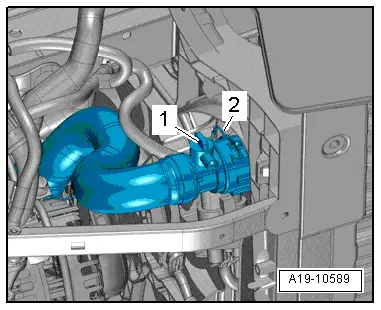
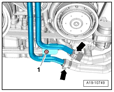
| Vehicles with coolant pipes (front left) (version 2): |
| –
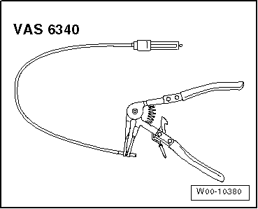
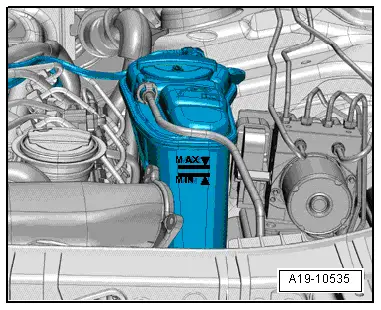
| Release hose clips -arrows-, disconnect coolant hoses from coolant pipes (front left) and drain off remaining coolant. |

Note
Note | t
| The cooling system is filled all year round with a mixture of water and coolant additive. |
| t
| Use only the coolant additive approved for this engine → Electronic parts catalogue. Other coolant additives could seriously impair in particular the anti-corrosion properties. The resulting damage could lead to loss of coolant and consequently to serious engine damage. |
| t
| Coolant additive prevents frost and corrosion damage and stops scaling. Such additives also raise the boiling point of the coolant. For these reasons the cooling system must be filled all year round with the correct coolant additive. |
| t
| Because of its high boiling point, the coolant improves engine reliability under heavy loads, particularly in countries with tropical climates. |
| t
| Frost protection is required down to about –25 °C (in countries with arctic climate: down to about –35 °C). |
| t
| The coolant concentration must not be reduced by adding water even in warmer seasons and in warmer countries. The antifreeze concentration must be at least 40 %. |
| t
| If greater frost protection is required in very cold climates, the concentration of coolant additive can be increased, but only up to 60% (this gives frost protection to –40 °C). If the concentration exceeds 60%, frost protection decreases again and cooling efficiency is impaired. |
| t
| Use only clean tap water for mixing coolant. |
| t
| Drained-off coolant must not be used again if the radiator, heat exchanger for heater, cylinder head, cylinder head gasket or cylinder block are renewed. |
| t
| Contaminated or dirty coolant must not be used again. |
| t
| Renew O-rings for bleeder screws on charge air coolers. |
| t
| For checking anti-freeze protection in cooling system, use refractometer -T10007-. |
|
|
|


 WARNING