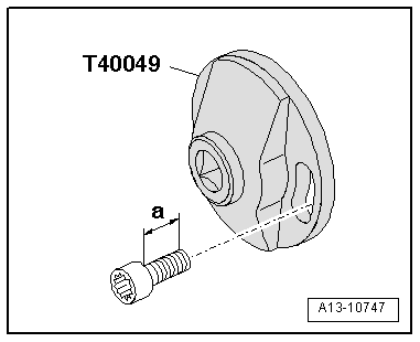
audi Workshop Repair Guides

Audi Workshop Service and Repair Manuals

Balance shaft - exploded view > < Drive chain for auxiliary drives - exploded view
Removing and installing drive chain for auxiliary drives
Special tools and workshop equipment required
   
t  Special wrench -T40049-
  W00-10043
t  Locking pin -T40069-
  W00-10207
t  Locking pin -T40071-
  W00-10238
t  Locating pins -T40116-
Removing
l  Gearbox removed → Rep. gr.34.
–  Remove timing chain cover (bottom) → Chapter.
  W00-10394
  Caution
Risk of damage to drive chain if thread of bolt exceeds specified length.
t  
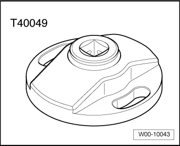
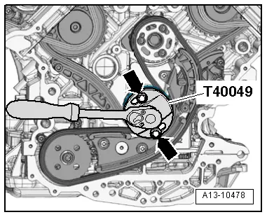
Use bolts with a maximum thread length -a- of 22 mm to attach special wrench -T40049-.
t  If no suitable bolts are available, position suitable washer(s) under bolt head so that remaining thread length does not exceed 22 mm.
  A13-10747
–  Attach special wrench -T40049- at rear end of crankshaft using 2 bolts -arrows-.
  A13-10478
–  Remove plug -arrow- for crankshaft „TDC“ marking from cylinder block.
–  Rotate crankshaft in normal direction of rotation to „TDC“.
  A15-10525
–  Screw locking pin -T40069- into hole (20 Nm); if necessary, turn crankshaft -1- backwards and forwards slightly to fully centralise locking pin.
  A13-10125
–  Press guide rail of chain tensioner in direction of -arrow- and lock chain tensioner by inserting locking pin -T40071-.
  Caution
If a used drive chain rotates in the opposite direction when it is refitted, this can cause breakage.
Mark running direction of drive chain with paint for re-installation. Do not attempt to mark the drive chain with a centre punch or by making a notch or similar.
–  Unscrew bolts -3- and detach chain sprocket from balance shaft.
–  Remove bolts -1- and -2- and take off chain tensioner with chain.
  A13-10479
Installing
l  Tightening torques → Chapter „Drive chain for auxiliary drives - exploded view“
l  Crankshaft -1- locked in „TDC“ position with locking pin -T40069-.
  A13-10125
–  Install chain tensioner with chain and balance shaft sprocket.
–  Lock balance shaft in „TDC“ position using locating pin -T40116-.
l  The elongated holes in the balance shaft sprocket must be aligned centrally over the threaded holes in the balance shaft. If necessary move chain one tooth further.
–  Tighten bolts for chain tensioner.
–  Fit bolts -1- for chain sprocket without tightening.
l  It should just be possible to turn the sprocket on the balance shaft without axial movement.
–  Pull out locking pin -T40071- to release chain tensioner.
–  Press against guide rail of chain tensioner -arrow- using a screwdriver, and at the same time tighten bolts -1- securing chain sprocket.
–  Pull locating pin -T40116- out of balance shaft.
Remaining installation steps are carried out in reverse sequence; note the following:
–  Install timing chain cover (bottom) → Chapter.
–  Install plug for crankshaft „TDC“ mark → Fig..
  A15-10756

Balance shaft - exploded view > < Drive chain for auxiliary drives - exploded view