
A4 Mk3
| Crankshaft - exploded view |
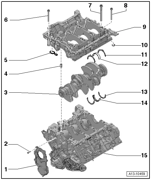
| 1 - | Sealing flange (pulley end) |
| q | Renewing → Chapter |
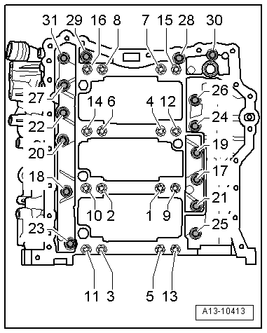
| 2 - | Bolt |
| q | Tightening torque and sequence → Fig. |
| 3 - | Crankshaft |
| q | Measuring axial clearance → Chapter |
| q | Measuring radial clearance → Chapter |
| q | Crankshaft dimensions → Chapter |
| 4 - | Dowel sleeve |
| q | 4x |
| q | Inserting in retaining frame → Fig. |
| 5 - | Seal |
| q | Renew |
| 6 - | Bolt |
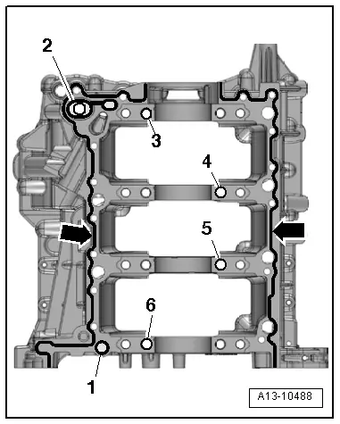
| q | For sealing surfaces: retaining frame to cylinder block |
| q | Differing bolt lengths and bolt heads |
| q | Tightening torque and sequence → Fig. |
| 7 - | Bolt (long, large collar) |
| q | For retaining frame (inner row) |
| q | Renew |
| q | Tightening torque and sequence → Fig. |
| 8 - | Bolt (short, small collar) |
| q | For retaining frame (outer row) |
| q | Tightening torque and sequence → Fig. |
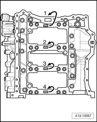
| 9 - | Retaining frame |
| q | With valve for oil pressure control -N428- → Fig. |
| q | To remove, detach guide rail → Item for drive chain for valve gear |
| q | Applying sealant → Fig. |
| q | Removing and installing valve for oil pressure control -N428- → Chapter |
| 10 - | Seal |
| q | Renew |
| 11 - | Thrust washer |
| q | Only fitted on 3rd crankshaft bearing |
| q | Installation position: oil groove faces outwards |
| q | Make sure it engages in retaining frame |
| 12 - | Bearing shell |
| q | For retaining frame (without oil groove) |
| q | Renew used bearing shells |
| q | Note installation position |
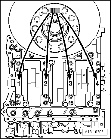
| q | Install new bearing shells for retaining frame with correct coloured markings → Fig. |
| 13 - | Thrust washer |
| q | Only fitted on 3rd crankshaft bearing |
| q | Installation position: oil groove faces outwards |
| q | Make sure it engages in retaining frame |
| 14 - | Bearing shell |
| q | For cylinder block (with oil groove) |
| q | Renew used bearing shells |
| q | Note installation position |
| q | Install new bearing shells for the cylinder block with the correct coloured markings → Fig. |
| 15 - | Cylinder block |
 Note
Note
|
|
|
|
Note
|
|
| Stage | Bolts | Tightening torque/angle specification |
| 1. | -1 … 16- | 50 Nm |
| 2. | -1 … 16- | turn 90° further |
| 3. | -17 … 31- | 23 Nm |
|
|
| Code letter on retaining frame | Colour coding of bearing | |
| R | = | Red |
| G | = | Yellow |
| B | = | Blue |
| S | = | Black |
|
|
| Letter on crankshaft | Colour coding of bearing | |
| R | = | Red |
| G | = | Yellow |
| B | = | Blue |
| S | = | Black |