audi Workshop Repair Guides

Audi Workshop Service and Repair Manuals

Drive unit - exploded view > < Securing supercharger to engine and gearbox support for leak test
Removing and installing charge air cooler
Special tools and workshop equipment required
   
t  Fitting sleeve -2033-
  W00-0774
t  Assembly device for valves -2036-
t  Tyre lever for aluminium rims -V.A.G 1942-
Removing
l  Supercharger secured to engine and gearbox support -VAS 6095- for assembly work → Chapter.
  W00-10141
Charge air cooler (left-side):
–  Unclip bracket -1- for vacuum hose.
  Note
Disregard -item 2-.
–  Remove charge pressure sender 2 -G447- → Chapter.
  A21-10367
Charge air cooler (right-side):
–  Remove throttle valve module -J338- → Rep. gr.24.
–  Remove charge pressure sender -G31- → Chapter.
  A24-10294
Continuation for both sides:
–  Remove bolts -1- and -2- and detach coolant pipes from supercharger.
  A19-10759
–  Remove bolts -1, 2- for charge air cooler (left-side) and bolts -3, 4- for charge air cooler (right-side).
  A21-10330
–  Attach valve assembly device -2036- with -2036/1- to supercharger, as shown in illustration.
–  Apply fitting sleeve -2033- at front of charge air cooler.
–  Using tyre lever -V.A.G 1942-, apply moderate pressure and slowly press charge air cooler out of supercharger housing.
  A21-10503
Installing
l  Tightening torques → Chapter „Charge air coolers - exploded view“
  Note
t  Renew seals, gaskets, O-rings and self-locking bolts.
t  Before assembly, always remove residues from threaded holes in supercharger housing using a thread tap.
–  Check gasket -5- on charge air cooler -4-.
l  The gasket must not be cracked or damaged.
–  Slide gasket -1- onto charge air cooler.
–  Insert O-ring -2- into opening in supercharger housing -3-.
  A21-10454
–  Coat sealing surface -arrow A- and gasket -arrow B- of charge air cooler -1- with engine oil.
–  Also coat sealing surface inside supercharger housing with engine oil.
  A21-10455
–  When fitting charge air cooler, make sure that seals align with recesses in supercharger housing -arrows-.
  Note
  A21-10504
To make it easier to insert and press in the charge air cooler, position the supercharger housing vertically in engine and gearbox support -VAS 6095-.
  Caution
Risk of damage to charge air cooler.
Only insert charge air cooler by hand.
–  Insert charge air cooler in supercharger housing -arrow A- by hand as far as stop, letting charge air cooler slide into hole -arrow B- in front of supercharger housing.
  A21-10456
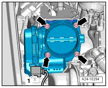
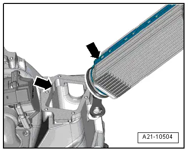
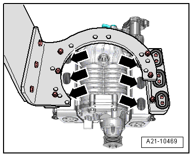
–  If necessary, guide charge air cooler by hand via openings -arrows- in supercharger housing when inserting cooler.
–  As soon as possible (due to length of bolts), screw in 2 bolts loosely by hand to guide charge air cooler additionally.
  Caution
Risk of damage to charge air cooler.
t  The charge air cooler must not be pulled in by screwing in the securing bolts.
t  
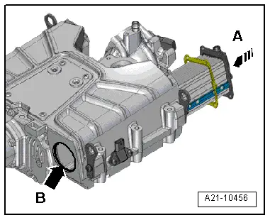
Insert charge air cooler by hand (without using tools) until sealing flange with gasket makes contact with supercharger housing (maximum: 1 mm distance). Only then tighten bolts, as described in the following.
  A21-10469
–  Tighten bolts -1, 2- for charge air cooler (left-side) and bolts -3, 4- for charge air cooler (right-side) in diagonal sequence and in small steps.
Remaining installation steps are carried out in reverse sequence; note the following:
–  Install coolant pipes on supercharger → Chapter.
–  Install throttle valve module -J338- → Rep. gr.24.
–  Check supercharger for leaks → Chapter.
  A21-10330

Drive unit - exploded view > < Securing supercharger to engine and gearbox support for leak test