
A4 Mk3
| Valve gear - exploded view |
 Note
Note| The diagram shows the cylinder head on cylinder bank 2 (left-side). |
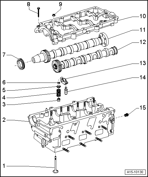
| 1 - | Valve |
| q | Do not machine, only grinding-in is permitted |
| q | Mark installation position for re-installation |
| q | Checking → Chapter |
| q | Valve dimensions → Chapter |
| q | Checking valve guides → Chapter |
| 2 - | Cylinder head |
| q | Checking valve guides → Chapter |
| q | Machining valve seats → Chapter |
| 3 - | Valve stem oil seal |
| q | Renewing with cylinder head installed → Chapter |
| q | Renewing with cylinder head removed → Chapter |
| 4 - | Valve spring |
| 5 - | Valve spring plate |
| 6 - | Valve cotters |
| 7 - | Camshaft oil seal |
| q | Renewing → Chapter |
| 8 - | Bolt |
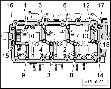
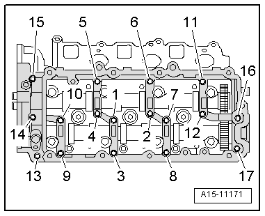
| q | Tightening torque and tightening sequence: cylinder head (left-side) → Fig., cylinder head (right-side) → Fig. |
| 9 - | Nut |
| q | Tightening torque and tightening sequence: cylinder head (left-side) → Fig., cylinder head (right-side) → Fig. |
| 10 - | Retaining frame |
| q | With integrated camshaft bearings |
| q | Removing and installing → Chapter „Removing and installing camshafts - cylinder head (left-side)“ |
| 11 - | Inlet camshaft |
| q | Removing and installing: cylinder head (left-side) → Chapter, cylinder head (right-side) → Chapter |
| q | Measuring axial clearance → Chapter |
| q | Measuring radial clearance → Chapter |
| q | Runout: max. 0.01 mm |
| 12 - | Exhaust camshaft |
| q | Removing and installing: cylinder head (left-side) → Chapter, cylinder head (right-side) → Chapter |
| q | Measuring axial clearance → Chapter |
| q | Measuring radial clearance → Chapter |
| q | Runout: max. 0.01 mm |
| 13 - | Roller rocker finger |
| q | Mark installation position for re-installation |
| q | Check roller bearings for ease of movement |
| q | Lubricate contact surfaces before installing |
| 14 - | Hydraulic valve compensation element |
| q | Mark installation position for re-installation |
| q | Checking → Chapter |
| q | Lubricate contact surfaces before installing |
| 15 - | Pressure limiting valve 1.0 bar |
| q | For lubricating points in cylinder head |
| q | Not applicable to more recent versions |
| q | 25 Nm |
|
|
| Stage | Bolts/nuts | Tightening torque | ||
| 1. | -1 … 18- | Screw in by hand until they make contact
| ||
| 2. | -1 … 18- | 9 Nm |
|
|
| Stage | Bolts/nuts | Tightening torque | ||
| 1. | -1 … 17- | Screw in by hand until they make contact
| ||
| 2. | -1 … 17- | 9 Nm |