
A4 Mk3
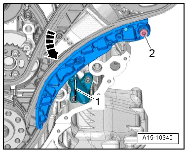
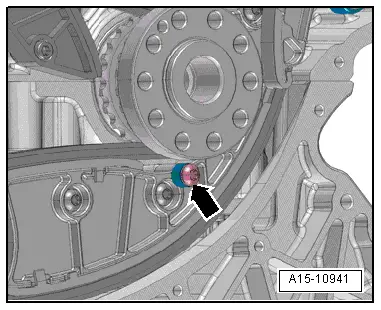
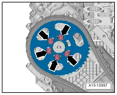
| Removing and installing camshaft timing chain |
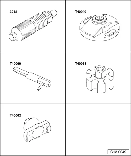
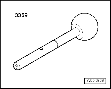
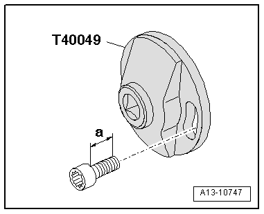
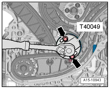
| Special tools and workshop equipment required |
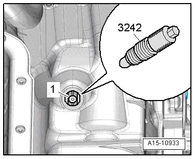
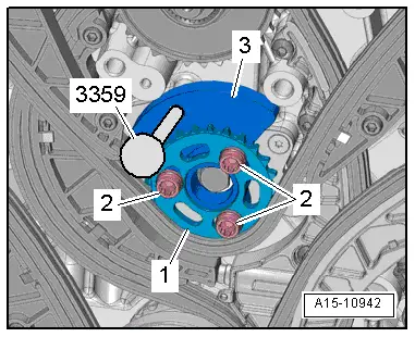
| t | Locking pin -3242- |
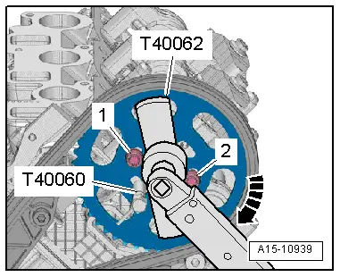
| t | Special wrench -T40049- |
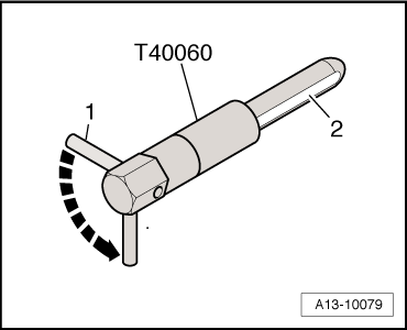
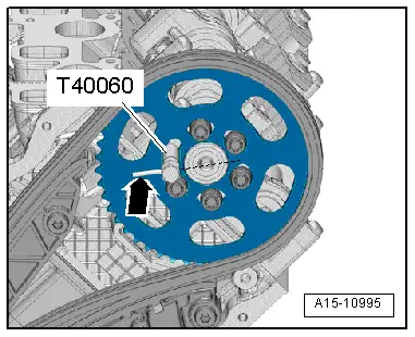
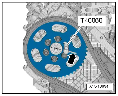
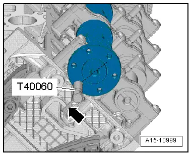
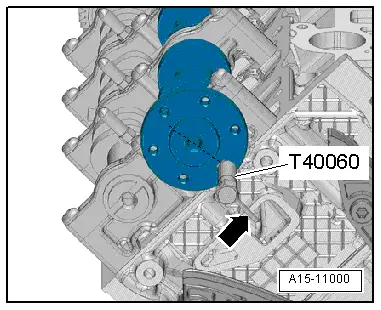
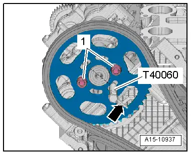
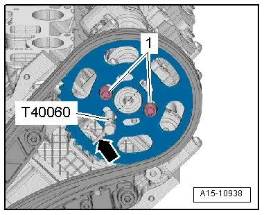
| t | 2x Adjustment pin -T40060- |
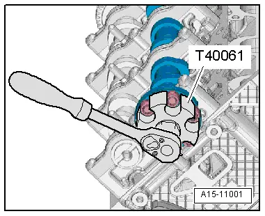
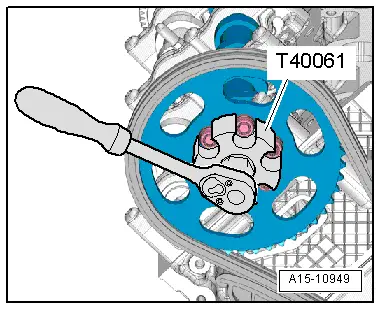
| t | Adapter -T40061- |
| t | Adapter -T40062- |
|
|
|
|
 Caution
|
|
 Note
Note |
|
|
|
|
|
|
|
|
|
|
|
|
|
|
|
|
|
|
|
Note
|
|
|
|
|
|
Note
|
|
|
|
|
|
|
|
Note
|
|
|
|
|
|
|
|
|
|
|
|
|
|
|
|
|
|
|
|