audi Workshop Repair Guides

Audi Workshop Service and Repair Manuals

Removing camshafts and re-installing used camshafts - cylinder bank 2 (left-side) > < Removing camshafts and re-installing used camshafts - cylinder bank 1 (right-side)
Removing and renewing camshafts or camshaft bearings - cylinder bank 1 (right-side)
Special tools and workshop equipment required
   
t  Counterhold tool -T10172- with adapter -T10172/5-
  W00-10637
t  Adjustment pin -T40060-
  W00-10242
t  Camshaft fitting tool -T40096-
  W00-10638
Removing
–  Remove timing chain from inlet camshaft → Chapter.
l  Crankshaft -1- locked in „TDC“ position with locking pin -3242-.
  A15-11026
–  Check „TDC“ position of camshafts:
l  It should be possible to lock the inlet camshaft -1- with the adjustment pin -T40060-.
l  The side pin -arrow- on the adjustment pin -T40060- must be in line with the imaginary line between the adjustment pin and the centre of the camshaft.
l  Exhaust camshaft -2- must be set so that groove -arrow B- is parallel above joint -arrow A- between bearing pedestal and bearing cap.
  A15-11033
–  Place camshaft fitting tool -T40096- on teeth of inlet camshaft so that the two arms of the tool engage on the two halves of the gear (one in each half, as shown in illustration).
l  The wider arm must engage in the wider half of the gear.
–  Tighten the clamping tool using the knurled wheel so that the faces of the gear teeth are in alignment.
  A15-10974
–  Pull off adjustment pin -T40060-.
–  Screw two bolts for camshaft chain sprocket five turns into threaded holes in camshaft, as shown in illustration.
  A15-11034
–  Fit counterhold tool -T10172- with adapter -T10172/5- on both bolts and turn camshafts approx. 30° in anti-clockwise direction -arrow- until groove -arrow A- in camshaft points vertically to sealing surface -arrows B- of cylinder head.
  Caution
Risk of damage to valves.
Do not turn camshafts any further than specified.
  A15-10957
–  Loosen bearing cap bolts in the sequence -12 ... 1-.
  Note
Make sure you do not damage the roller rocker fingers and hydraulic compensation elements when removing the camshafts.
–  Carefully detach bearing caps and camshafts.
  A15-11032
Installing
l  Tightening torques → Chapter „Valve gear - exploded view“
l  Crankshaft locked in „TDC“ position with locking pin -3242-.
–  Place camshaft fitting tool -T40096- on teeth of inlet camshaft so that the two arms of the tool engage on the two halves of the gear (one in each half, as shown in illustration).
l  The wider arm must engage in the wider half of the gear.
–  Tighten the clamping tool using the knurled wheel so that the faces of the gear teeth are in alignment.
  A15-10974
To prevent installation at the wrong locations, the camshaft bearing pedestals and bearing caps for cylinder bank 1 are marked at the factory on the exhaust side:
  A15-11006
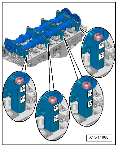
Cylinder bank 1 (right-side)
R1/R1Front
R2/R2Front centre
R3/R3Rear centre
R4/R4Rear

   
–  Fit camshaft bearing pedestals „I, II and III“ on cylinder head.
l  The oil drillings -arrow 1- in the cylinder head must be in line with the oil passages -arrow 2- in the bearing pedestals.
  A15-10975
–  Fit camshaft bearing pedestal „IV“ on cylinder head.
l  Both dowel sleeves -arrows- must be inserted in holes in bearing pedestal.
l  Dowel sleeves must engage in holes in cylinder head.
  A15-10976
–  Check that bearing pedestals are positioned correctly:
l  The round side -arrow 2- faces the inlet side.
l  The square side -arrow 1- faces the exhaust side.
  A15-10977
–  Insert camshafts in bearing pedestals in „TDC“ position.
l  It should be possible to lock the inlet camshaft -1- with the adjustment pin -T40060-.
l  The side pin -arrow- on the adjustment pin -T40060- must be in line with the imaginary line between the adjustment pin and the centre of the camshaft.
l  Exhaust camshaft -2- must be set so that groove -arrow A- is parallel above joint -arrow B- between bearing pedestal and bearing cap.
–  Fit matching bearing caps on bearing pedestals.
  A15-11033
–  Wrap one cable tie -arrows- on each side around bearing pedestal and bearing cap and secure.
  Note
The cable ties help to keep the camshafts and camshaft bearings straight when they are tightened.
  A15-10956
–  Pull off adjustment pin -T40060-.
–  Screw two bolts for camshaft chain sprocket five turns into threaded holes in camshaft, as shown in illustration.
  A15-11034
–  Fit counterhold tool -T10172- with adapter -T10172/5- on both bolts and turn camshafts approx. 30° in anti-clockwise direction -arrow- until groove -arrow A- in camshaft points vertically to sealing surface -arrows B- of cylinder head.
  Caution
Risk of damage to valves.
Do not turn camshafts any further than specified.
  A15-10957
–  Tighten bearing cap bolts → Fig..
  A15-11032
–  Fit counterhold tool -T10172- with adapter -T10172/5- on both bolts and turn camshafts approx. 30° in clockwise direction -arrow- until groove -arrow A- in camshaft is aligned with hole -arrow B- for adjustment pin -T40060-.
  A15-11002
–  Check „TDC“ position of camshafts:
l  It should be possible to lock the inlet camshaft -1- with the adjustment pin -T40060-.
l  The side pin -arrow- on the adjustment pin -T40060- must be in line with the imaginary line between the adjustment pin and the centre of the camshaft.
l  Exhaust camshaft -2- must be set so that groove -arrow A- is parallel above joint -arrow B- between bearing pedestal and bearing cap.
Remaining installation steps are carried out in reverse sequence; note the following:
–  Remove camshaft fitting tool -T40096-.
–  Install camshaft timing chains → Chapter.
  Caution
Avoid damage to valves and piston crowns after working on valve gear.
t  The hydraulic tappets have to settle; wait for approx. 30 minutes after installing camshafts before starting engine.
t  Turn the engine carefully at least 2 rotations to ensure that none of the valves make contact when the starter is operated.
  A15-11033

Removing camshafts and re-installing used camshafts - cylinder bank 2 (left-side) > < Removing camshafts and re-installing used camshafts - cylinder bank 1 (right-side)