
A4 Mk3
| Valve gear - exploded view |
 Note
Note| Illustration shows the cylinder head for cylinder bank 2 (left-side). |
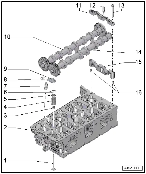
| 1 - | Valve |
| q | Do not machine, only grinding-in is permitted |
| q | Mark installation position for re-installation |
| q | Checking → Chapter |
| q | Valve dimensions → Chapter |
| q | Checking valve guides → Chapter |
| 2 - | Cylinder head |
| q | Checking valve guides → Chapter |
| q | Machining valve seats → Chapter |
| 3 - | Valve stem oil seal |
| q | Renewing with cylinder head installed → Chapter |
| q | Renewing with cylinder head removed → Chapter |
| 4 - | Valve spring |
| 5 - | Valve spring plate |
| 6 - | Valve cotters |
| 7 - | Hydraulic valve compensation element |
| q | Clipped into roller rocker finger -item 9- |
| q | Checking → Chapter |
| q | Mark installation position for re-installation |
| q | Lubricate contact surfaces before installing |
| 8 - | Securing clip |
| q | Not supplied separately |
| q | Check for firm attachment |
| 9 - | Roller rocker finger |
| q | Mark installation position for re-installation |
| q | Check roller bearings for ease of movement |
| q | Lubricate contact surfaces before installing |
| q | Assembly: attach to hydraulic compensation element -item 7- using securing clip -item 8- |
| 10 - | Inlet camshaft |
| q | Removing and installing: |
| t | → Chapter „Removing camshafts and re-installing used camshafts - cylinder bank 1 (right-side)“ |
| t | → Chapter „Removing and renewing camshafts or camshaft bearings - cylinder bank 1 (right-side)“ |
| t | → Chapter „Removing camshafts and re-installing used camshafts - cylinder bank 2 (left-side)“ |
| t | → Chapter „Removing and renewing camshafts or camshaft bearings - cylinder bank 2 (left-side)“ |
| q | Measuring axial clearance → Chapter |
| q | Measuring radial clearance → Chapter |
| q | Runout: max. 0.01 mm |
| 11 - | Bearing cap |
| q | Removing and installing → Chapter „Removing camshafts and re-installing used camshafts - cylinder bank 1 (right-side)“ |
| q | Note installation position |
| 12 - | Support bracket |
| q | For clamping piece |
| q | Tightening torque → Rep. gr.23 |
| 13 - | Bolt |
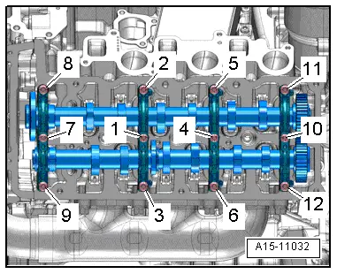
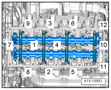
| q | Tightening torque and tightening sequence: cylinder bank 1 (right-side) → Fig., cylinder bank 2 (left-side) → Fig. |
| 14 - | Exhaust camshaft |
| q | Removing and installing: |
| t | → Chapter „Removing camshafts and re-installing used camshafts - cylinder bank 1 (right-side)“ |
| t | → Chapter „Removing and renewing camshafts or camshaft bearings - cylinder bank 1 (right-side)“ |
| t | → Chapter „Removing camshafts and re-installing used camshafts - cylinder bank 2 (left-side)“ |
| t | → Chapter „Removing and renewing camshafts or camshaft bearings - cylinder bank 2 (left-side)“ |
| q | Measuring axial clearance → Chapter |
| q | Measuring radial clearance → Chapter |
| q | Runout: max. 0.01 mm |
| 15 - | Bearing pedestal |
| q | Removing and installing: |
| t | → Chapter „Removing camshafts and re-installing used camshafts - cylinder bank 1 (right-side)“ |
| t | → Chapter „Removing camshafts and re-installing used camshafts - cylinder bank 2 (left-side)“ |
| q | Note installation position |
| 16 - | Spring pins |
| q | Only for bearing pedestal (rear) with camshaft axial bearing |
|
|
| Stage | Bolts | Tightening torque |
| 1. | -1 … 12- | Screw in bolts by hand until they make contact |
| 2. | -1 … 12- | 9 Nm |
|
|
| Stage | Bolts | Tightening torque |
| 1. | -1 … 12- | Screw in bolts by hand until they make contact |
| 2. | -1 … 12- | 9 Nm |