audi Workshop Repair Guides

Audi Workshop Service and Repair Manuals

Oil filter housing, oil pressure switches, engine oil cooler > < Removing and installing valve for oil pressure controlN428
Removing and installing sump (top section)
Special tools and workshop equipment required
   
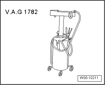
t  Used oil collection and extraction unit -V.A.G 1782-
t  Safety goggles
t  Electric drill with plastic brush
t  Sealant → Electronic parts catalogue
Removing
l  Engine removed and secured to engine and gearbox support → Chapter
l  Engine oil drained → Booklet811, → Booklet812 or → Booklet818.
–  Remove timing chain cover (bottom) → Chapter.
–  Remove drive chain for oil pump and high-pressure pump → Chapter.
–  Remove sealing flange (pulley end) → Chapter.
–  Remove oil pump → Chapter.
  W00-10211
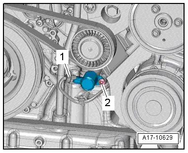
–  Unplug electrical connector -1- at valve for oil pressure control -N428-.
  Note
Disregard -item 2-.
  A17-10629
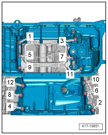
–  Slacken and remove bolts in the sequence: -12 ... 1-.
–  Carefully release sump (top section) from bonded joint, pry sump off dowel sleeves and detach.
Installing
  Note
Renew gaskets, seals and O-rings.
  Caution
Protect lubrication system against contamination.
Cover exposed parts of the engine.
  A17-10651
  WARNING
Protect eyes against injuries.
Wear safety goggles.
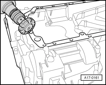
–  Remove remaining sealant from sump (top section) and cylinder block using rotating plastic brush or similar.
–  Clean sealing surfaces; they must be free of oil and grease.
  Note
  A17-0161
Note the use-by date of the sealant.
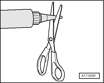
–  Cut off nozzle of tube at front marking (nozzle Ø approx. 3 mm).
  A17-0081
–  Fit seals -1- and -2- in sump (top section).
  Caution
Make sure lubrication system is not clogged by excess sealant.
The sealant bead must not be thicker than specified.
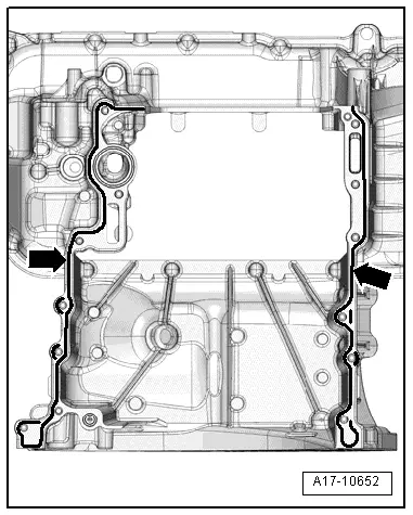
–  Apply beads of sealant -arrows- onto clean sealing surface of sump (top section) as shown in illustration.
l  The grooves on the sealing surfaces must be completely filled with sealant.
l  The beads of sealant must project 3.5 mm above the sealing surface.
  Note
The sump (top section) must be installed within 5 minutes after applying the sealant.
–  Fit sump (top section) and tighten bolts → Fig..
Remaining installation steps are carried out in reverse sequence; note the following:
–  Install coolant pipe (rear left) → Chapter.
–  Install oil pump → Chapter.
–  Install sealing flange (pulley end) → Chapter.
–  Install drive chain for oil pump and high-pressure pump → Chapter.
–  Install timing chain cover (bottom) → Chapter.
  A17-10652

Oil filter housing, oil pressure switches, engine oil cooler > < Removing and installing valve for oil pressure controlN428