audi Workshop Repair Guides

Audi Workshop Service and Repair Manuals

Control unit for reducing agent metering system - exploded view > < Reservoir for reducing agent - exploded view
Removing and installing reservoir for reducing agent
Special tools and workshop equipment required
   
t  Special wrench -T50014-
Removing
Observe safety precautions → Chapter.
Observe rules for cleanliness → Chapter.
–  Remove active tank for reducing agent → Chapter.
  W00-10459
–  Press release tabs -arrows-, unplug electrical connectors -1- and -2- and unclip from bracket.
  A20-10706
  WARNING
Safety risk due to escaping reducing agent.
Observe safety measures for handling reducing agent → Chapter.
  Note
Hold a clean cloth under the separating point to catch escaping reducing agent.
–  Press release catches and disconnect return line -1- and supply line -4- → Chapter.
–  Move electrical wiring clear.
–  Unscrew union nut -3- using special wrench -T50014- and carefully lift off reservoir -2-.
  WARNING
Safety risk due to escaping reducing agent.
Keep in mind that the active tank and the reservoir still contain a little reducing agent.
Installing
l  Tightening torques → Chapter „Reservoir for reducing agent - exploded view“
  Note
t  Renew seal.
t  Thoroughly clean sealing surfaces for seal.
  A20-10707
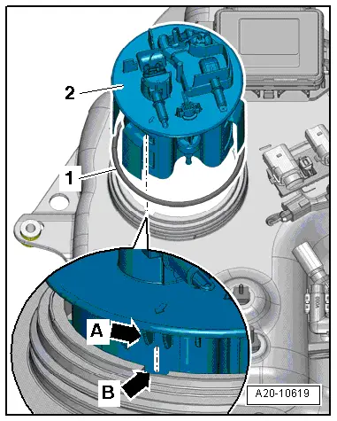
–  Insert reservoir -2- in active tank; while doing so, carefully slide heating element into active tank through gap between reservoir and installation opening.
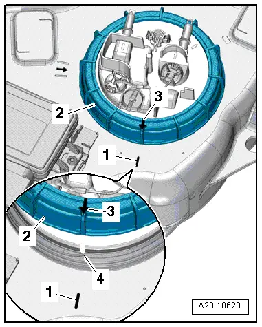
–  Slip new seal -1- onto reservoir and press it until it makes contact at installation opening.
l  The seal must not be twisted.
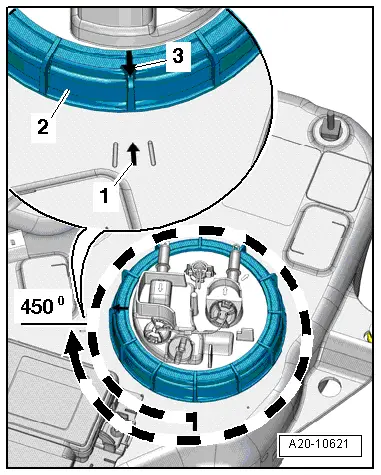
–  Move reservoir into installation position:
l  Lug -arrow A- on reservoir must engage in groove -arrow B- on edge of installation opening of active tank.
  A20-10619
–  Position union nut -2- so that mark -3- is positioned above the first thread -4-. At this position there is an arrow -1- on the active tank.
–  First tighten new union nut by hand and then use special wrench -T50014- to tighten it a total of 5/4 turns (450°).
  A20-10620
l  Mark -3- on new union nut -2- and mark -1- (arrow with a line on each side) must be aligned.
Remaining installation steps are carried out in reverse sequence; note the following:
–  Install active tank for reducing agent → Chapter.
–  Adapt learnt value after draining reducing agent or renewing components → Chapter.
  A20-10621

Control unit for reducing agent metering system - exploded view > < Reservoir for reducing agent - exploded view