
A4 Mk3
|
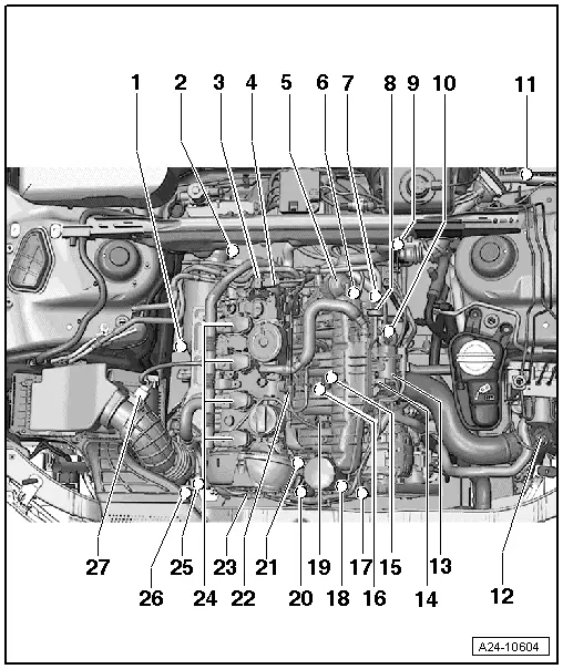
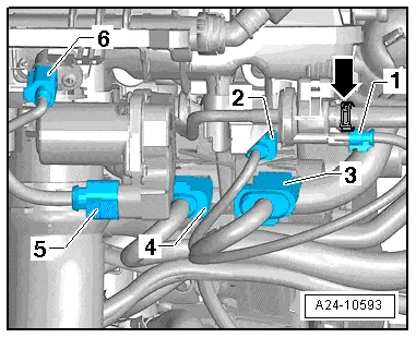
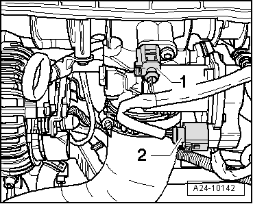
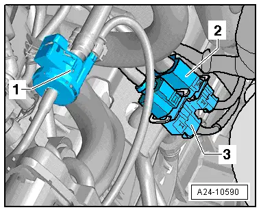
| 1 - | Lambda probe -G39- and Lambda probe heater -Z19- |
| q | Fitting location → Fig. |
| q | Removing and installing → Chapter |
| 2 - | Lambda probe after catalytic converter -G130- and Lambda probe heater 1 after catalytic converter -Z29- |
| q | Fitting location → Fig. |
| q | Removing and installing → Chapter |
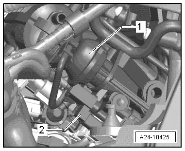
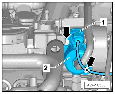
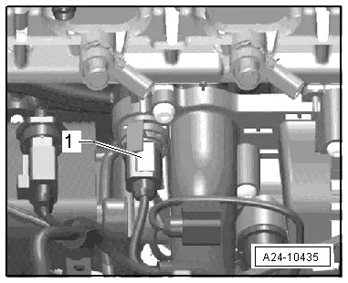
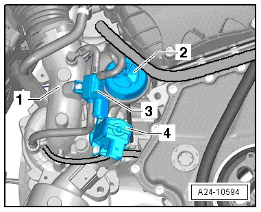
| 3 - | Fuel pressure regulating valve -N276- |
| q | Fitting location → Fig. |
| 4 - | High-pressure pump |
| q | Removing and installing → Fig. |
| 5 - | Vacuum unit for air flow control flaps (intake manifold flaps) |
| q | Fitting location → Fig. |
| 6 - | Intake manifold flap valve -N316- |
| q | Fitting location → Fig. |
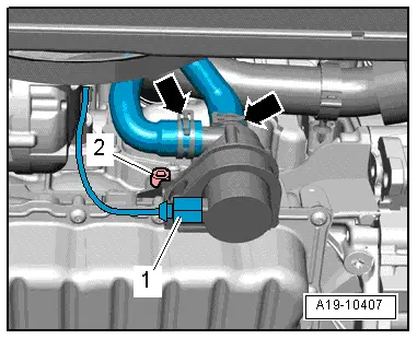
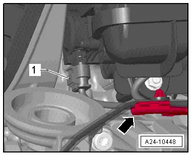
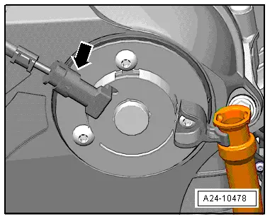
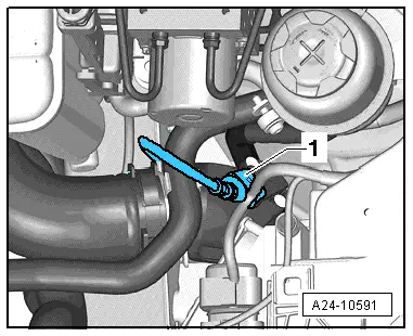
| 7 - | Engine speed sender -G28- |
| q | Fitting location → Fig. |
| q | 4.5 Nm |
| 8 - | Activated charcoal filter solenoid valve 1 -N80- |
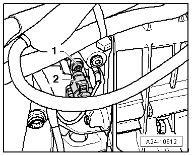
| 9 - | 6-pin connectors |
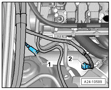
| q | For Lambda probe -G39- and Lambda probe heater -Z19- (black) |
| q | Lambda probe after catalytic converter -G130- and Lambda probe 1 heater after catalytic converter -Z29- (brown connector) |
| q | Fitting location → Fig. |
| 10 - | Electrical connectors for |
| q | Knock sensor 1 -G61- |
| q | Intake manifold flap valve -N316- |
| q | Fuel pressure sender -G247- |
| q | Intake manifold flap potentiometer -G336- |
| q | Coolant temperature sender -G62- |
| q | Hall sender -G40- |
| q | Injectors -N30- ... -N33- |
| q | Fitting location → Fig. |
| 11 - | Engine control unit -J623- |
| q | Fitting location → Fig. |
| q | Removing and installing → Chapter |
| 12 - | Charge pressure sender -G31- |
| q | Fitting location → Fig. |
| q | Removing and installing → Rep. gr.21 |
| 13 - | Throttle valve module -J338-, throttle valve drive (electric throttle operation) -G186- |
| q | Throttle valve drive angle sender 1 -G187- and throttle valve drive angle sender 2 -G188- |
| q | Throttle valve module -J338- must always be re-adapted to engine control unit -J623- after removal and installation or if it has been renewed |
| q | Fitting location → Fig. |
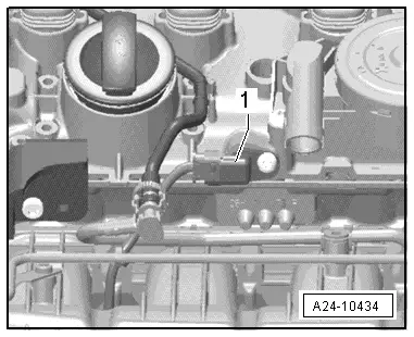
| 14 - | Intake air temperature sender -G42- |
| q | Fitting location → Fig. |
| 15 - | Knock sensor 1 -G61- |
| q | To remove, first remove coolant pump with thermostat |
| q | 20 Nm |
| q | Removing and installing → Chapter |
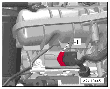
| 16 - | Coolant temperature sender -G62- |
| q | Fitting location → Fig. |
| 17 - | Valve for oil pressure control -N428- |
| q | Fitting location → Fig. |
| q | Removing and installing → Rep. gr.17 |
| 18 - | Oil pressure switch for reduced oil pressure -F378- |
| q | Fitting location → Fig. |
| q | Removing and installing → Rep. gr.17 |
| 19 - | Fuel pressure sender -G247- |
| q | Fitting location → Fig. |
| q | Removing and installing → Chapter |
| 20 - | Oil pressure switch -F22- |
| q | Fitting location → Fig. |
| q | Removing, installing and testing → Rep. gr.17 |
| 21 - | Intake manifold flap potentiometer -G336- |
| q | Fitting location → Fig. |
| 22 - | Hall sender -G40- (camshaft position sensor) |
| q | Fitting location → Fig. |
| 23 - | Camshaft control valve 1 -N205- |
| q | Fitting location → Fig. |
| q | Removing and installing → Rep. gr.15 |
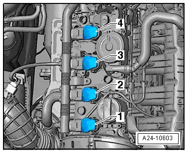
| 24 - | Ignition coils with output stages |
| q | Fitting location → Fig. |
| q | Puller -T40039- is required for removing ignition coils from cylinder head. |
| q | Removing and installing → Chapter |
| 25 - | Turbocharger air recirculation valve -N249- |
| q | Located directly on turbocharger → Fig. |
| q | Removing and installing → Rep. gr.21 |
| 26 - | Charge pressure control solenoid valve -N75- |
| q | Located directly on turbocharger → Fig. |
| q | Removing and installing → Rep. gr.21 |
| 27 - | Air mass meter -G70- |
| q | Removing and installing → Chapter |
| A - | Diagnostic connector |
| q | In driver's knee restraint |
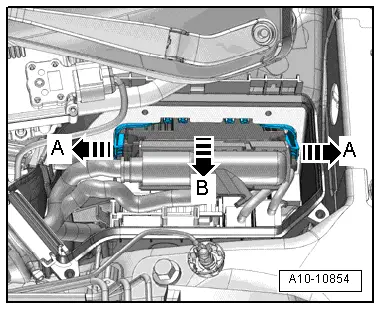
| B - | Fuel pump control unit -J538- |
| q | Fitting location → Fig. |
| q | Removing and installing → Rep. gr.20 |
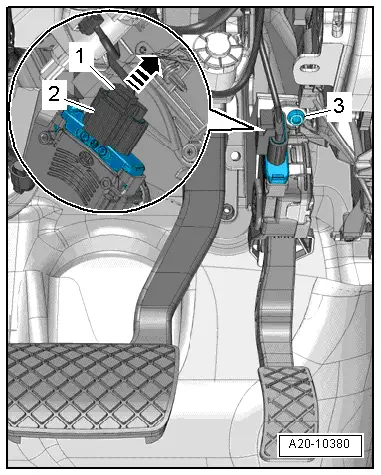
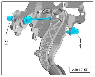
| C - | Brake light switch - F- and brake pedal switch -F47- |
| q | Fitting location → Fig. |
| q | In footwell on brake pedal |
| q | Removing and installing → Rep. gr.45 |
| D - | Clutch position sender -G476- |
| q | Only fitted on vehicles with manual gearbox |
| q | Fitting location → Fig. |
| E - | Accelerator position sender -G79- and accelerator position sender 2 -G185- |
| q | Fitting location → Fig. |
| q | On accelerator pedal (both senders are accommodated in one housing) |
| q | Removing and installing → Rep. gr.20 |
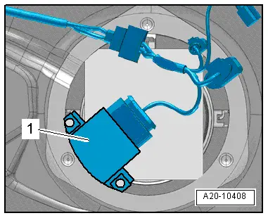
| F - | Radiator fan control unit -J293- |
| q | Incorporated in radiator fan |
| G - | Injectors |
| q | In fuel rail |
| q | Injector, cylinder 1 -N30- |
| q | Injector, cylinder 2 -N31- |
| q | Injector, cylinder 3 -N32- |
| q | Injector, cylinder 4 -N33- |
| q | Removing and installing → Chapter |
| H - | Continued coolant circulation pump -V51- |
| q | For hot countries only |
| q | Fitting location → Fig. |
| q | Removing and installing → Rep. gr.19 |
| I - | Left electrohydraulic engine mounting solenoid valve -N144- |
| q | Not installed in all vehicles (depends on gearbox type) |
|
|
|
|
|
|
|
|
|
|
|
|
|
|
|
|
|
|
|
|
|
|
|
|
|
|
|
|
|
|
|
|
|
|
|
|
|
|
|
|
|
|
|
|