audi Workshop Repair Guides

Audi Workshop Service and Repair Manuals

Checking fuel gauge senderG > < Checking fuel delivery rate of fuel system pressurisation pumpG6 (in fuel tank)
Removing and installing fuel delivery unit
Special tools and workshop equipment required
   
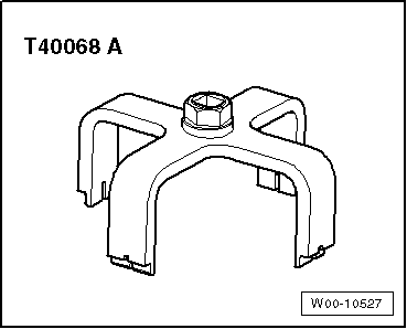
t  Union nut tool -T40068 A-
Removing
–  Observe safety precautions → Chapter.
–  Observe rules for cleanliness → Chapter.
  WARNING
Large amounts of fuel can escape.
The fuel tank must not be more than 1/4 full when removing the fuel delivery unit, otherwise a large amount of fuel will escape.
–  Drain fuel tank if necessary → Chapter.
–  Move passenger's seat as far to front as possible (if necessary).
  W00-10527
–  Remove rear seat bench → Rep. gr.72.
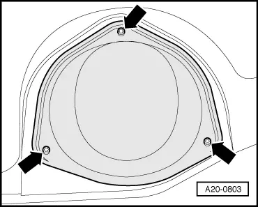
–  Unscrew cover for flange -arrows-.
  A20-0803
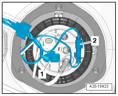
–  Unplug electrical connector -1- on flange.
Vehicles with auxiliary heater:
–  Disengage electrical connector -2- for metering pump for auxiliary heater on flange and move clear.
  A20-10423
All vehicles (continued):
  WARNING
The fuel can become extremely hot. This can cause injuries.
t  In extreme cases the fuel lines and the fuel can reach a temperature of 100 °C. Allow the fuel to cool down before disconnecting the lines - danger of scalding.
t  Wear protective gloves.
t  Wear safety goggles.
Risk of injury - fuel system operates under high pressure.
To reduce the pressure in the fuel system, wrap a clean cloth around the connection and carefully loosen the connection.
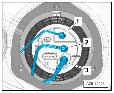
–  Press release tabs and disconnect fuel lines -2- and -3- on flange.
Vehicles with auxiliary heater:
–  Press release tab and disconnect fuel line -1- leading to metering pump for auxiliary heater at flange.
  A20-10424
All vehicles (continued):
  WARNING
Large amounts of fuel can escape.
The fuel tank must not be more than 1/4 full when removing the fuel delivery unit, otherwise a large amount of fuel will escape.
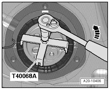
–  Unscrew union nut using union nut tool -T40068 A--arrow-.
  Note
The plastic detent on the threaded ring will break off when the union nut is unscrewed - this can be disregarded.
  A20-10406
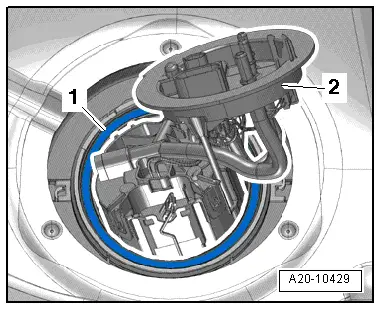
–  Take flange -2- out of fuel tank and detach seal -1-.
  A20-10429
  WARNING
Safety risk from escaping fuel: the fuel delivery unit is still filled.
Use a cloth to catch escaping fuel.
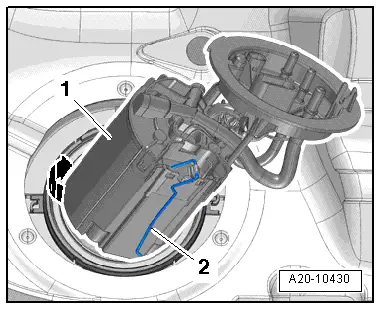
–  Swivel fuel delivery unit -1- to left side of vehicle -arrow- and tilt slightly out of fuel tank.
  Note
When removing fuel delivery unit, make sure you do not bend float arm of fuel gauge sender -G-.
–  Pull fuel gauge sender -G--item 2- out of opening in fuel tank and remove fuel delivery unit with suction pipe from fuel tank.
Installing
Installation is carried out in the reverse order; note the following:
l  Tightening torque → Chapter „Fuel delivery unit and fuel gauge sender - exploded view“
  Note
t  Renew seal and union nut.
t  Take care not to bend float arm of fuel gauge sender -G- when fitting fuel delivery unit.
t  Ensure that fuel hoses are securely seated.
  A20-10430
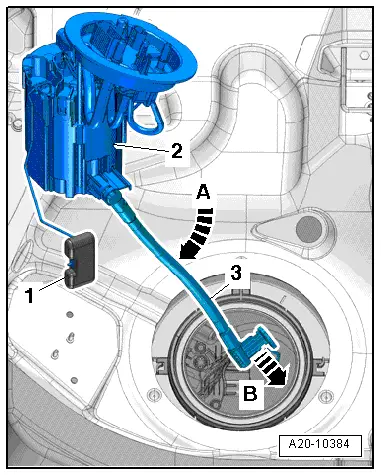
–  Pivot suction pipe -3- on fuel delivery unit -2- downwards -arrow A-.
–  First guide suction pipe into fuel tank -arrow B-.
–  Then insert float -1- on fuel gauge sender -G- into fuel tank.
  A20-10384
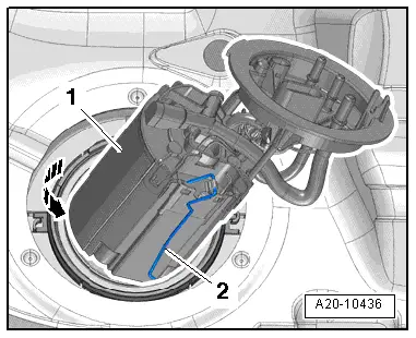
–  Swivel fuel delivery unit -1- to left side of vehicle and guide into fuel tank -arrow- (make sure fuel gauge sender -2- is not damaged).
  A20-10436
–  Slip new seal -1- onto flange -2- and insert in groove on fuel tank.
  A20-10429
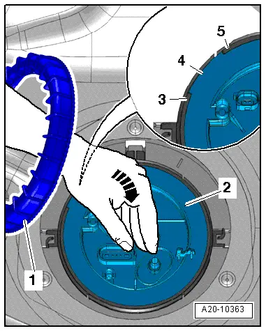
–  Slip union nut -1- over your left arm and press flange -2- firmly into installation position -arrow- with your left hand.
l  Lug -4- on flange must be between tabs -3- and -5- on threaded ring.
  A20-10363
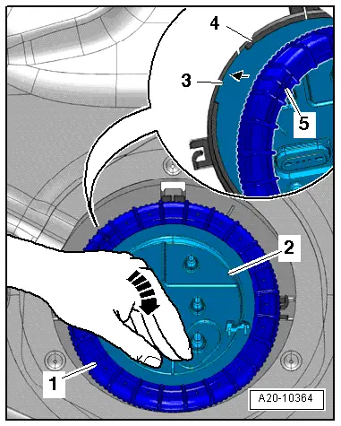
–  Take union nut -1- off your left arm with your right hand and at the same time keep pressing down flange -2- firmly with your left hand -arrow-.
–  Position union nut -1- with your right hand in such a way that double ridge -5- on ribs aligns with lug -3- of flange (approx. „ten o'clock position“). This will make union nut engage immediately with beginning of thread -4- when tightening.
  A20-10364
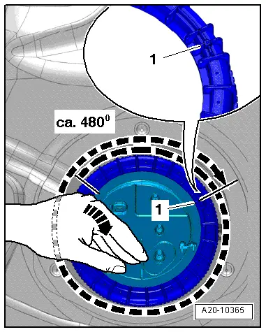
–  Keep pressing flange downwards firmly -arrow-.
–  Turn union nut approx. 480° with your right hand until double ridge -1- is in approx. „two o'clock position“ and at the same time keep on pressing flange downwards firmly with your left hand.
  A20-10365
  Caution
Take care to avoid leakage at flange.
Press flange downwards firmly when tightening union nut to make sure flange does not also turn.
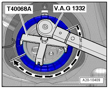
–  Tighten union nut for flange using union nut tool -T40068 A-.
  A20-10409
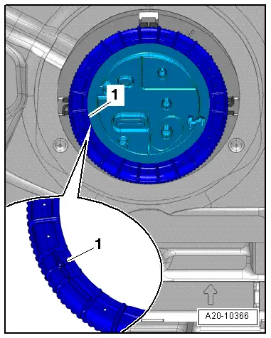
l  Checking: Double ridge -1- must now be aligned between „seven o'clock and eight o'clock position“.
  A20-10366
–  Connect fuel lines -1, 2, 3-.
–  Connect electrical connectors.
–  Install cover for flange → Fig..
–  Install rear seat bench → Rep. gr.72.
–  Put at least 5 litres of fuel into tank after installing fuel delivery unit.
Vehicles with auxiliary heater:
–  Bleed fuel supply line leading to metering pump → Chapter.
  A20-10424

Checking fuel gauge senderG > < Checking fuel delivery rate of fuel system pressurisation pumpG6 (in fuel tank)