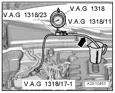
audi Workshop Repair Guides

Audi Workshop Service and Repair Manuals

Checking fuel pump delivery rate - vehicles with 6-cylinder FSI engine > < Removing and installing fuel pump control unitJ538
Checking fuel pump delivery rate - vehicles with 4-cylinder TFSI engine
   
Checking fuel pump delivery rate - vehicles with 4-cylinder TFSI engine
Special tools and workshop equipment required
t  K-Jetronic pressure tester -V.A.G 1318-
t  Adapter -V.A.G 1318/11-
t  Adapter -V.A.G 1318/17-1- from adapter set -V.A.G 1318/17-
t  Connector -V.A.G 1318/23-
t  Remote control -V.A.G 1348/3A- for V.A.G 1348 with adapter cable -V.A.G 1348/3-3-
t  Auxiliary measuring set -V.A.G 1594C-
t  Fuel-resistant measuring container

   
Procedure
–  Observe test conditions → Chapter.
–  Remove rear seat bench → Rep. gr.72.
–  Unscrew cover for flange -arrows-.
  A20-0803
–  Unplug electrical connector -1- on flange.
  A20-10454
–  Connect remote control -V.A.G 1348/3A- for V.A.G 1348 to contact -1- using adapter cable -V.A.G 1348/3-3- and test lead from auxiliary measuring set -V.A.G 1594C-.
–  Tape off 2nd connector contact of adapter cable -V.A.G 1348/3-3- with insulating tape -arrow- to prevent short circuits.
–  Connect contact -5- to vehicle body (earth) using a test lead from auxiliary measuring set -V.A.G 1594C-.
–  Move switch of remote control -V.A.G 1348/3A- for V.A.G 1348 to front of engine compartment.
  A20-10373
Vehicles up to 05.2008:
–  Unclip plenum chamber cover -2- and remove.
  Note
Disregard -items 1, 3- and -arrow-.
  A92-10115
Vehicles from 06.2008 onwards:
–  Lift off cover -1- by its handle -arrow-.
  A27-10221
All vehicles (continued):
–  Release retainer -arrow A- and open cover -arrow B-.
  A10-10851
–  Connect crocodile clip to jump start socket -U6--item A- in terminal 30 wiring junction 2 -TV22- located in plenum chamber.
–  Remove filler cap from fuel filler neck.
  A20-10373
  WARNING
Risk of injury - fuel system operates under high pressure.
To reduce the pressure in the fuel system, wrap a clean cloth around the connection and carefully loosen the connection.
–  Disconnect fuel line -2- by pulling release ring -1-.
  A20-10457
–  Screw connector -V.A.G 1318/23- and adapter -V.A.G 1318/17-1- onto K-Jetronic pressure tester -V.A.G 1318-.
–  Fit adapter -V.A.G 1318/17-1- onto disconnected fuel supply line.
–  Screw adapter -V.A.G 1318/11- onto K-Jetronic pressure tester -V.A.G 1318-.
–  Attach test hose -arrow- and hold end of hose in measuring container.
–  Open cut-off valve on pressure tester.
l  Lever must point in direction of flow.
–  Build up pressure in fuel system by pressing remote control switch and slowly closing cut-off valve on pressure tester.
l  Specification: 4 bar
–  From this point on do not move position of cut-off valve.
–  Drain measuring container.
  A20-10453
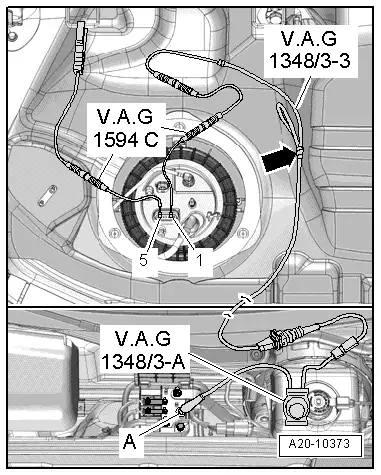
–  Press remote control switch for 15 seconds.
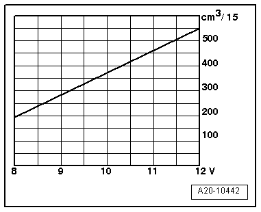
–  Compare amount of fuel delivered with minimum delivery shown in diagram (cm3/15 sec.).
  Note
Voltage at fuel pump with engine stationary and pump running is approx. 2 volts less than battery voltage.
If minimum delivery rate is not achieved, check for the following causes:
t  Fuel lines have been crushed.
t  Fuel filter is blocked.
t  Fuel pump is defective.
Installation is carried out in the reverse order; note the following:
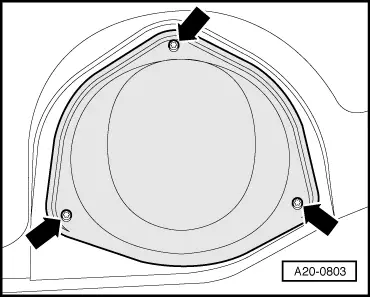
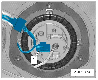
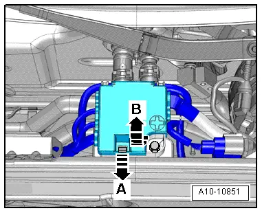
–  Install cover for flange → Fig..
–  Install rear seat bench → Rep. gr.72.
  A20-10442

Checking fuel pump delivery rate - vehicles with 6-cylinder FSI engine > < Removing and installing fuel pump control unitJ538