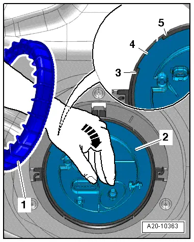
WARNING | Safety risk from escaping fuel: the fuel delivery unit is still filled. |
| Use a cloth to catch escaping fuel. |
|
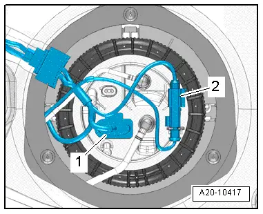
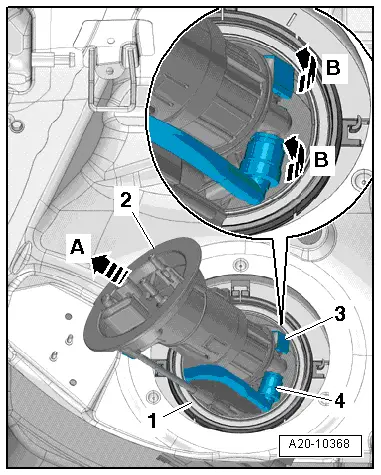
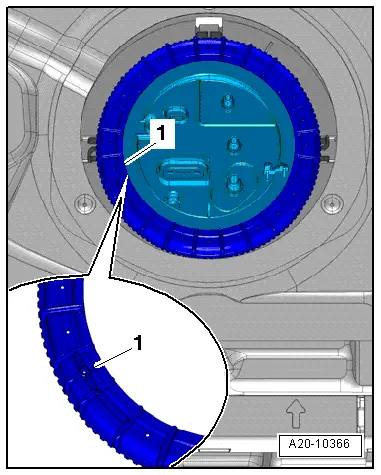
| –
| Pull flange -2- with fuel filter a bit further away from fuel delivery unit -1--arrow A-. |
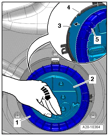
| –
| Swivel fuel delivery unit to left side of vehicle -arrow B- and tilt slightly out of fuel tank. |

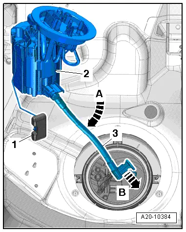
Note | When removing fuel delivery unit, make sure you do not bend float arm of fuel gauge sender -G-. |
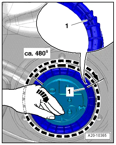
| –
| Pull fuel gauge sender -G--item 3- out of opening in fuel tank and remove fuel delivery unit with suction pipe from fuel tank. |
| Installation is carried out in the reverse order; note the following: |
Note | t
| Renew seal and union nut. |
| t
| When installing fuel delivery unit, take care not to bend float arm of fuel gauge sender -G-. |
| t
| Make sure that fuel lines are securely fitted. |
|
|

|
 Caution