
A4 Mk3
| Overview of fitting locations |
| Engine compartment (right-side) |

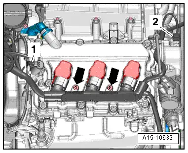
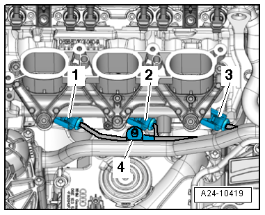
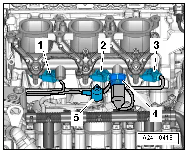
| 1 - | Ignition coils for cylinder bank 1 |
| q | Ignition coil 1 with output stage -N70- |
| q | Ignition coil 2 with output stage -N127- |
| q | Ignition coil 3 with output stage -N291- |
| q | Removing and installing → Chapter |
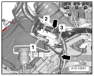
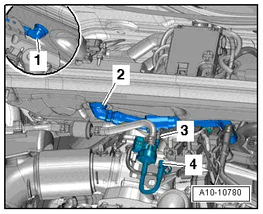
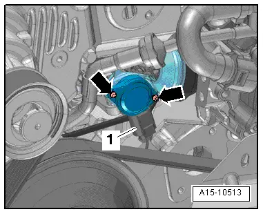
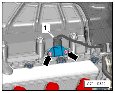
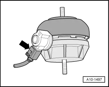
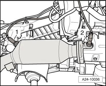
| 2 - | Lambda probe -G39- with Lambda probe heater -Z19- |
| q | Fitting location → Fig. |
| q | Fitting location of connector → Fig. |
| q | Removing and installing → Chapter |
| q | 55 Nm |
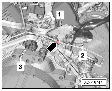
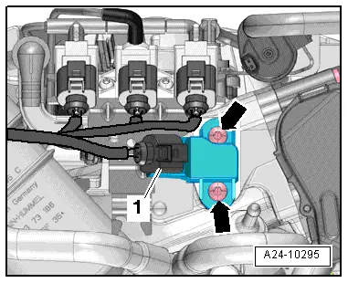
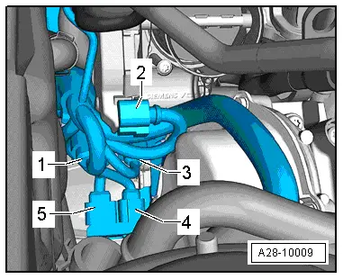
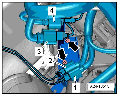
| 3 - | Camshaft control valve 1 -N205- |
| q | Fitting location → Fig. |
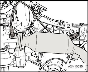
| 4 - | Lambda probe after catalytic converter -G130- with Lambda probe 1 heater after catalytic converter -Z29- |
| q | Fitting location → Fig. |
| q | Fitting location of connector → Fig. |
| q | Removing and installing → Chapter |
| q | 55 Nm |
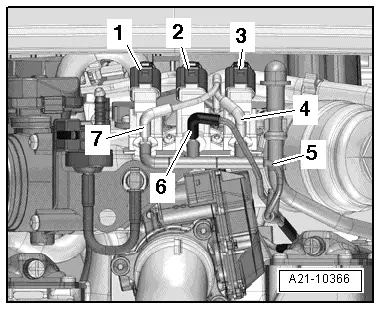
| 5 - | Sender 1 for secondary air pressure -G609- |
| q | Only on USA models |
| q | Fitting location → Rep. gr.26 |
| 6 - | Secondary air inlet valve -N112- |
| q | Fitting location → Fig. |
| 7 - | Intake air temperature sender -G42- / intake manifold pressure sender -G71- |
| 8 - | Intake manifold flap valve -N316- |
| q | Fitting location → Fig. |
| 9 - | Activated charcoal filter solenoid valve 1 -N80- |
| q | Fitting location → Fig. |
| 10 - | Secondary air inlet valve 2 -N320- |
| q | Fitting location → Fig. |
| 11 - | Regulating flap control unit -J808- |
| q | Fitting location → Fig. |
| q | After renewing regulating flap control unit -J808-, perform Adaption in Guided Functions → vehicle diagnostic tester. |
| q | Removing and installing → Chapter |
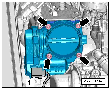
| 12 - | Throttle valve module -J338- |
| q | Fitting location → Fig. |
| q | After renewing throttle valve module -J338-, perform Adaption in Guided Functions → vehicle diagnostic tester. |
| q | Removing and installing → Chapter |
| 13 - | Knock sensor 1 -G61- |
| q | Fitting location → Fig. |
| q | Fitting location of connector → Fig. |
| 14 - | Injectors, cylinder bank 1 |
| q | Injector, cylinder 1 -N30- |
| q | Injector, cylinder 2 -N31- |
| q | Injector, cylinder 3 -N32- |
| q | Removing and installing → Chapter |
| 15 - | Intake manifold flap potentiometer -G336- |
| q | Fitting location → Fig. |
| 16 - | Hall sender -G40- |
| q | Fitting location → Fig. |
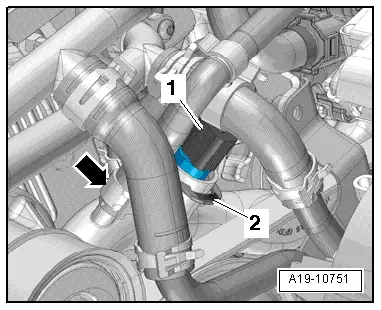
| 17 - | Charge pressure sender -G31- / intake manifold temperature sender -G72- |
| q | Fitting location → Fig. |
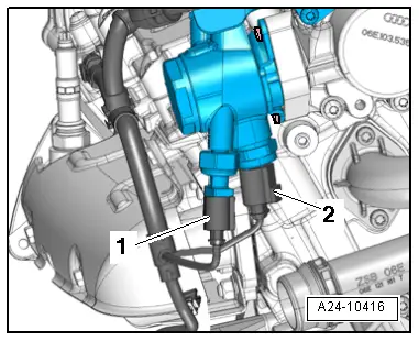
| 18 - | High-pressure pump |
| q | With fuel metering valve -N290- |
| q | With fuel pressure sender for low pressure -G410- |
| q | Fitting location → Fig. |
| q | Removing and installing → Chapter |
| 19 - | Secondary air pump motor -V101- |
| q | Fitting location → Fig. |
| Engine compartment (left-side) |

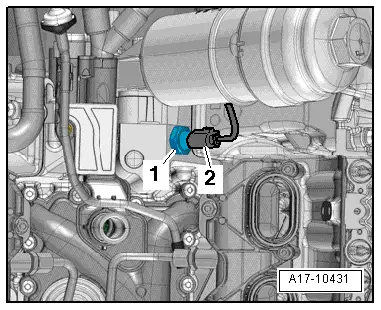
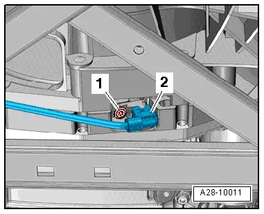
| 1 - | Fuel pressure sender -G247- |
| q | Fitting location → Fig. |
| q | 22 Nm |
| q | Lubricate threads |
| 2 - | Knock sensor 2 -G66- |
| q | Fitting location → Fig. |
| q | Fitting location of connector → Fig. |
| 3 - | Injectors, cylinder bank 2 |
| q | Injector, cylinder 4 -N33- |
| q | Injector, cylinder 5 -N83- |
| q | Injector, cylinder 6 -N84- |
| q | Removing and installing → Chapter |
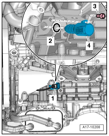
| 4 - | Oil pressure switch for reduced oil pressure -F378- |
| q | Fitting location → Fig. |
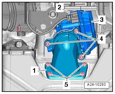
| 5 - | Regulating flap control unit -J808- |
| q | Fitting location → Fig. |
| q | Removing and installing → Chapter |
| – | After renewing regulating flap control unit -J808-, perform Adaption in Guided Functions → vehicle diagnostic tester. |
| 6 - | Secondary air inlet valve -N112- |
| q | Fitting location → Fig. |
| 7 - | Intake air temperature sender -G42- / intake manifold pressure sender -G71- |
| q | Fitting location → Fig. |
| 8 - | Intake manifold flap valve -N316- |
| q | Fitting location → Fig. |
| 9 - | Activated charcoal filter solenoid valve 1 -N80- |
| 10 - | Secondary air inlet valve 2 -N320- |
| q | Fitting location → Fig. |
| 11 - | Oil pressure switch -F22- |
| q | Fitting location → Fig. |
| 12 - | Engine speed sender -G28- |
| q | Fitting location → Fig. |
| q | Removing and installing → Chapter |
| q | 9 Nm |
| 13 - | Lambda probe 2 after catalytic converter -G131- with Lambda probe 2 heater after catalytic converter -Z30- |
| q | Fitting location → Fig. |
| q | Fitting location of connector → Fig. |
| q | Removing and installing → Chapter |
| q | 55 Nm |
| 14 - | Camshaft control valve 2 -N208- |
| Fitting location → Fig. |
| 15 - | Lambda probe 2 -G108- with Lambda probe heater 2 -Z28- |
| q | Fitting location → Fig. |
| q | Fitting location of connector → Fig. |
| q | Removing and installing → Chapter |
| q | 55 Nm |
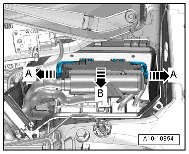
| 16 - | Engine control unit -J623- |
| q | Fitting location → Fig. |
| q | Removing and installing → Chapter |
| – | After renewing, perform Adaption in Guided Functions → vehicle diagnostic tester |
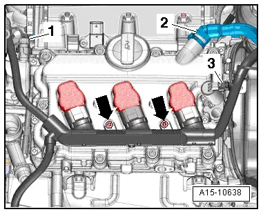
| 17 - | Ignition coils for cylinder bank 2 |
| q | Ignition coil 4 with output stage -N292- |
| q | Ignition coil 5 with output stage -N323- |
| q | Ignition coil 6 with output stage -N324- |
| q | Removing and installing → Chapter |
| 18 - | Valve for oil pressure control -N428- |
| q | Fitting location → Fig. |
| 19 - | Continued coolant circulation pump -V51- |
| q | Not installed on certain equipment versions or on vehicles for certain export markets |
| q | Fitting location → Fig. |
| 20 - | Intake manifold temperature sender 2 -G430- / charge pressure sender 2 -G447- |
| q | Fitting location → Fig. |
| 21 - | Hall sender 2 -G163- |
| q | Fitting location → Fig. |
| 22 - | Intake manifold flap potentiometer 2 -G512- |
| q | Fitting location → Fig. |
| q | After renewing, perform Adaption in Guided Functions → vehicle diagnostic tester |
| 23 - | Coolant temperature sender -G62- |
| q | Fitting location → Fig. |
|
|
 Note
Note
|
|
Note
|
|
|
|
|
|
|
|
|
|
|
|
|
|
|
|
|
|
|
|
|
|
|
|
|
|
Note
|
|
|
|
|
|
|
|
Note
|
|
|
|
|
|
|
|
|
|
|
|
|
|
Note
|
|