| t
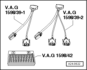
| Test box -V.A.G 1598/42- |

Note | t
| The test box has 105 sockets. The connecting cable can be disconnected from the test box. This means that only the cable (and not the test box) has to be purchased for future engine control units with different types of connectors. |
| t
| The smaller of the two connectors on the engine control unit has the contacts 1 to 60. The larger of the two connectors has the contacts 1 to 94. |
| t
| If you want to check a wiring connection to the engine control unit, first refer to the current flow diagram to find out which connector on the engine control unit the wiring connection leads to. If the wire goes to the 60-pin connector, connect the smaller of the two connectors -V.A.G 1598/39-1- to input „A“ of test box -V.A.G 1598/42-. |
| t
| The test box -V.A.G 1598/42- is designed so it can be connected both to the wiring harness for the engine control unit and to the engine control unit itself at the same time. |
| t
| The advantage of this is that the electronic engine control system remains fully functional when the test box is connected (for example, for measuring signals when the engine is running). |
| t
| The relevant test procedure will state whether it is necessary to also connect the engine control unit to the test box. |

WARNING | To prevent damage to the electronic components, select the appropriate test range before connecting the test leads and observe the test requirements. |
|
| –
| Remove engine control unit -J623- → Chapter. |
| –
| Connect test box -V.A.G 1598/42- to wiring harness with adapter cable -V.A.G 1598/39-1- or adapter cable -V.A.G 1598/39-2-. Connect earth clip of test box to negative terminal of battery. The instructions for performing the individual tests indicate whether or not the engine control unit itself also needs to be connected to the test box. |
| –
| Carry out test as described in appropriate repair procedures. |
| Installing engine control unit |
| Installation is performed in the reverse sequence. |
| –
| Make sure you fit metal casing back on engine control unit -J623-. |
| –
| Always use new shear bolts. |
| –
| Clean threaded holes for new shear bolts to remove any residue from locking fluid. This can be done using a thread tap. |
| After installing a new engine control unit, the following operation must be performed: |
| –
| Activate engine control unit via a vehicle diagnostic tester in „Guided Functions“ mode, „Replace engine control unit“. |
|
|
|
