
A4 Mk3
| Overview of fitting locations |
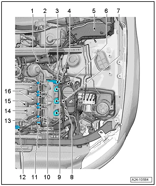
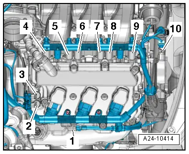
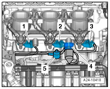
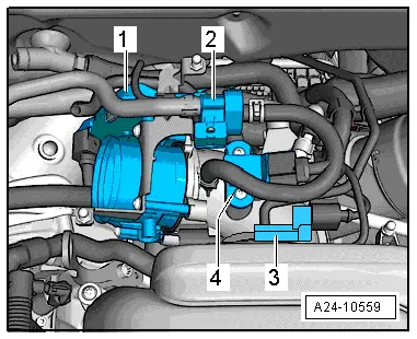
| Engine compartment (right-side) |

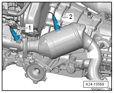
| 1 - | Lambda probe -G39- |
| q | Fitting location → Fig. |
| q | Fitting location of electrical connector → Fig. |
| q | Removing and installing → Chapter |
| q | 55 Nm |
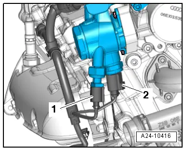
| 2 - | Exhaust camshaft control valve 1 -N318- |
| q | Fitting location → Fig. |
| q | Renew O-ring |
| q | 2.5 Nm |
| 3 - | Camshaft control valve 1 -N205- |
| q | Fitting location → Fig. |
| q | Renew O-ring |
| q | 2.5 Nm |
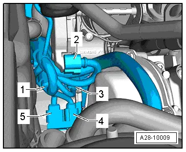
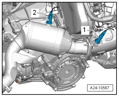
| 4 - | Lambda probe after catalytic converter -G130- |
| q | Fitting location → Fig. |
| q | Fitting location of connector → Fig. |
| q | Removing and installing → Chapter |
| q | 55 Nm |
| 5 - | Connectors |
| q | For injectors, cylinder bank 1 |
| q | For throttle valve module -J338- |
| q | For knock sensor 1 -G61- |
| q | For Lambda probe -G39- |
| q | For Lambda probe after catalytic converter -G130- |
| q | Fitting locations of connectors → Fig. |
| 6 - | Throttle valve module -J338- |
| q | Including throttle valve drive for electric throttle -G186-, throttle valve drive angle sender 1 for electric throttle -G187- and throttle valve drive angle sender 2 for electric throttle -G188- |
| q | After renewing, perform adaption in „Guided Functions“, option „Adapt throttle valve module“ |
| q | Fitting location → Fig. |
| 7 - | Activated charcoal filter solenoid valve 1 -N80- |
| 8 - | Intake air temperature sender -G42- / intake manifold pressure sender -G71- |
| q | Fitting location → Fig. |
| 9 - | Injector, cylinder bank 1 |
| q | Injector, cylinder 3 -N32- |
| q | Fitting location → Fig. |
| q | Removing and installing → Chapter |
| 10 - | Knock sensor 1 -G61- |
| q | Fitting location → Fig. |
| q | Fitting location of electrical connector → Fig. |
| q | Removing and installing → Chapter |
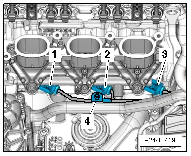
| 11 - | Injectors, cylinder bank 1 |
| q | Injector, cylinder 1 -N30- |
| q | Injector, cylinder 2 -N31- |
| q | Fitting location → Fig. |
| q | Removing and installing → Chapter |
| 12 - | Variable intake manifold position sender -G513- |
| 13 - | Variable intake manifold change-over valve -N156- |
| q | Fitting location → Fig. |
| 14 - | Actuator for intake manifold changeover |
| q | Vacuum unit |
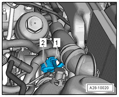
| 15 - | Coolant temperature sender -G62- |
| q | Fitting location → Fig. |
| 16 - | Hall sender -G40- |
| q | Fitting location → Fig. |
| q | Renew O-ring |
| q | 9 Nm |
| q | Removing and installing → Chapter |
| 17 - | Actuators for camshaft adjustment |
| q | Actuator 1 for camshaft adjustment -F366- |
| q | Actuator 2 for camshaft adjustment -F367- |
| q | Actuator 3 for camshaft adjustment -F368- |
| q | Actuator 4 for camshaft adjustment -F369- |
| q | Actuator 5 for camshaft adjustment -F370- |
| q | Actuator 6 for camshaft adjustment -F371- |
| q | Fitting location → Fig. |
| 18 - | High-pressure pump |
| q | With fuel pressure sender, low pressure -G410- and fuel metering valve -N290- |
| q | Fitting location → Fig. |
| q | Removing and installing → Chapter |
| 19 - | Ignition coils for cylinder bank 1 |
| q | Ignition coil 1 with output stage -N70- |
| q | Ignition coil 2 with output stage -N127- |
| q | Ignition coil 3 with output stage -N291- |
| q | Removing and installing → Chapter |
| 20 - | Hall sender 3 -G300- |
| q | Fitting location → Fig. |
| q | Renew O-ring |
| q | 9 Nm |
| q | Removing and installing → Chapter |
| 21 - | Secondary air pump motor -V101- |
| q | Not installed in all vehicles (only EU 5) |
| q | Removing and installing → Rep. gr.26 |
| 22 - | Variable intake manifold change-over valve -N335- |
| q | Not installed in all vehicles |
|
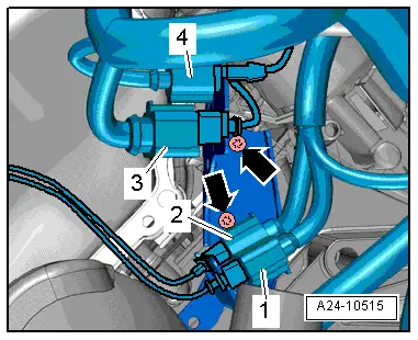
| 1 - | Bracket (left-side) for connectors |
| q | For knock sensor 2 -G66- |
| q | For injectors, cylinder bank 2 |
| q | For fuel pressure sender -G247- |
| q | Fitting locations of connectors → Fig. |
| 2 - | Lambda probe 2 after catalytic converter -G131- |
| q | Fitting location → Fig. |
| q | Fitting location of electrical connector → Fig. |
| q | Removing and installing → Chapter |
| q | 55 Nm |
| 3 - | Camshaft control valve 2 -N208- |
| q | Fitting location → Fig. |
| q | Renew O-ring |
| q | 2.5 Nm |
| 4 - | Exhaust camshaft control valve 2 -N319- |
| q | Fitting location → Fig. |
| q | Renew O-ring |
| q | 2.5 Nm |
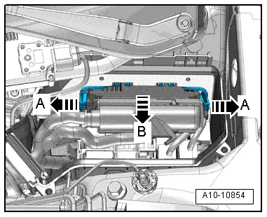
| 5 - | Engine control unit -J623- |
| q | Fitting location → Fig. |
| q | Removing and installing → Chapter |
| 6 - | Lambda probe 2 -G108- |
| q | Fitting location → Fig. |
| q | Fitting location of electrical connector → Fig. |
| q | Removing and installing → Chapter |
| q | 55 Nm |
| 7 - | Hall sender 4 -G301- |
| q | Fitting location → Fig. |
| q | Renew O-ring |
| q | 9 Nm |
| q | Removing and installing → Chapter |
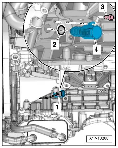
| 8 - | Valve for oil pressure control -N428- |
| q | Fitting location → Fig. |
| q | Removing and installing → Rep. gr.17 |
| 9 - | Ignition coils for cylinder bank 2 |
| q | Ignition coil 4 with output stage -N292- |
| q | Ignition coil 5 with output stage -N323- |
| q | Ignition coil 6 with output stage -N324- |
| q | Removing and installing → Chapter |
| 10 - | Actuators for camshaft adjustment |
| q | Actuator 7 for camshaft adjustment -F372- |
| q | Actuator 8 for camshaft adjustment -F373- |
| q | Actuator 9 for camshaft adjustment -F374- |
| q | Actuator 10 for camshaft adjustment -F375- |
| q | Actuator 11 for camshaft adjustment -F376- |
| q | Actuator 12 for camshaft adjustment -F377- |
| q | Fitting location → Fig. |
| 11 - | Hall sender 2 -G163- |
| q | Fitting location → Fig. |
| q | Renew O-ring |
| q | 9 Nm |
| q | Removing and installing → Chapter |
| 12 - | Variable intake manifold position sender -G513- |
| q | Fitting location → Fig. |
| 13 - | Injector, cylinder bank 2 |
| q | Injector, cylinder 4 -N33- |
| 14 - | Fuel pressure sender -G247- |
| q | Fitting location → Fig. |
| 15 - | Knock sensor 2 -G66- |
| q | Fitting location → Fig. |
| q | Fitting location of connector → Fig. |
| q | Removing and installing → Chapter |
| 16 - | Injectors, cylinder bank 2 |
| q | Injector, cylinder 5 -N83- |
| q | Injector, cylinder 6 -N84- |
| q | Fitting location → Fig. |
| q | Removing and installing → Chapter |
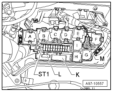
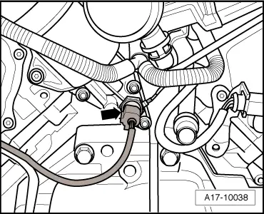
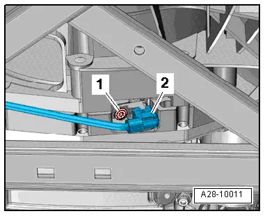
| A - | Engine speed sender -G28- |
| q | Fitting location → Fig. |
| q | Removing and installing → Chapter |
| q | 9 Nm |
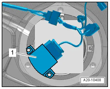
| B - | Fuel pump control unit -J538- |
| q | Fitting location → Fig. |
| q | Removing and installing → Rep. gr.20 |
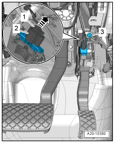
| C - | Accelerator position sender -G79- and accelerator position sender 2 -G185- |
| q | In footwell on accelerator pedal (both senders are accommodated in one housing) |
| q | Fitting location → Fig. |
| q | Removing and installing → Rep. gr.20 |
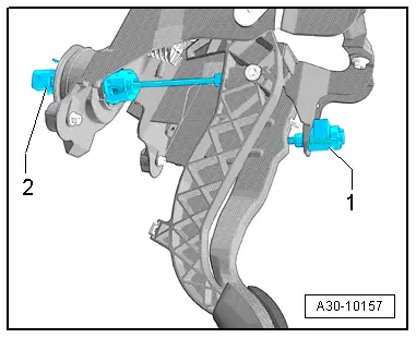
| D - | Brake light switch -F-/brake pedal switch -F47- |
| q | In footwell on brake pedal |
| q | Removing and installing → Rep. gr.45 |
| q | Fitting location → Fig. |
| E - | Clutch position sender -G476- |
| q | Only fitted on vehicles with manual gearbox |
| q | Fitting location → Fig. |
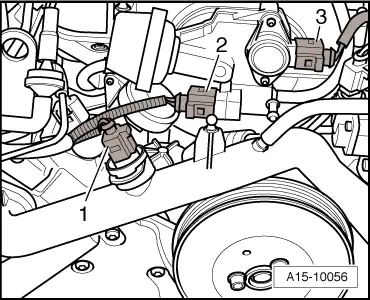
| F - | Oil pressure switch -F22- |
| q | Fitting location → Fig. |
| q | Removing, installing and testing → Rep. gr.17 |
| G - | Oil pressure switch for reduced oil pressure -F378- |
| q | Fitting location → Fig. |
|
|
|
|
|
|
|
|
|
|
|

|
|
|
|
|
|
|
|

|
|
|
|
|
|
|
|
|
|
|
|
|
|
|
|
|
|
|
|
|