audi Workshop Repair Guides

Audi Workshop Service and Repair Manuals

Removing and installing bottom section of intake manifold (right-side) > < Removing and installing intake manifold (top section)
Removing and installing bottom section of intake manifold (left-side)
Removing
  WARNING
t  Always read rules for cleanliness and instructions for working on fuel system → Chapter.
t  Follow these instructions and rules for cleanliness before starting work and while working on the fuel system.
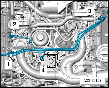
Vehicles with engine codes CAMA, CAMB, CCWA, CCWB, CGKA, CGKB, CCLA:
   
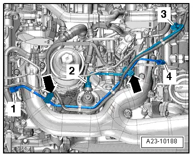
–  Unscrew bolts -arrows- and remove retaining clips.
–  Unscrew union nuts -1 ... 4- and detach high-pressure pipes.
Vehicles with engine code CAPA:
  A23-10188
–  Unscrew union nuts -1- and -3-.
–  Move high-pressure pipes clear and detach.
  Note
Disregard item -2-.
All vehicles (continued):
–  Remove top section of intake manifold → Chapter.
  A23-10128
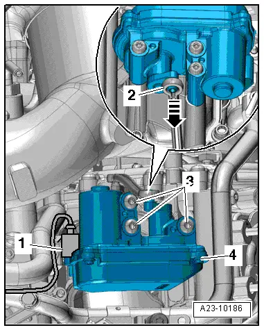
–  Carefully press connecting rod -2- off intake manifold flap 2 motor -V275- in direction of -arrow- (observe note).
  Note
Proceed carefully when pressing connecting rod off ball stud (risk of breaking).
–  Unplug electrical connector -1-.
–  Unscrew bolts -3- and detach intake manifold flap motor -V275--item 4-.
–  Unplug electrical connectors for glow plugs on cylinders 4, 5 and 6.
–  Take exhaust gas recirculation cooler change-over valve -N345--item 1- out of bracket.
Vehicles with engine codes CAPA, CAMA, CAMB:
  A23-10186
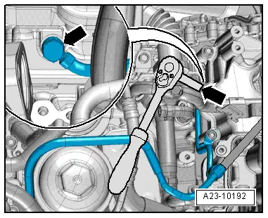
–  Use jointed wrench to unscrew banjo bolt -arrow- securing coolant bleeder pipe.
Vehicles with engine codes CCWA, CCWB, CGKA, CGKB, CCLA:
  A23-10192
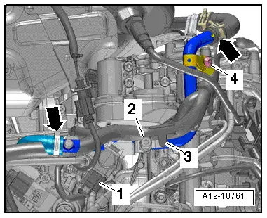
–  Remove bolt -4-.
  A19-10761
–  Release clamp -arrow- and detach exhaust gas recirculation pipe -1-.
All vehicles (continued):
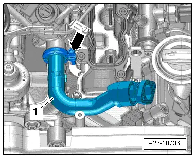
  A26-10736
–  Remove bolts -arrows-.
–  Press coolant bleeder pipe to one side and detach bottom section of intake manifold (left-side) to the front.
  Note
Block off intake ports in cylinder head with a clean rag.
Installing
l  Tightening torques: refer to intake manifold - exploded view → Chapter
Installation is carried out in the reverse order; note the following:
  Note
Renew seals and gaskets.
–  Before installing intake manifold (bottom section), screw in banjo bolt for coolant bleeder pipe 2 to 3 turns with new seals (only for vehicles with engine codes CAPA, CAMA, CAMB).
–  Tighten banjo bolt for coolant bleeder pipe to 15.5 Nm.
–  Install top section of intake manifold → Chapter.
–  Install high-pressure pipes → Chapter.
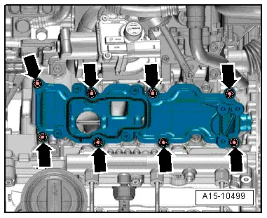
  A15-10499

Removing and installing bottom section of intake manifold (right-side) > < Removing and installing intake manifold (top section)