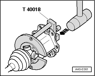
| –
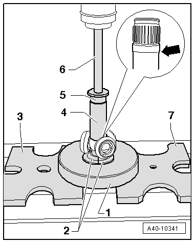
| Press triple roller spider off drive shaft. |
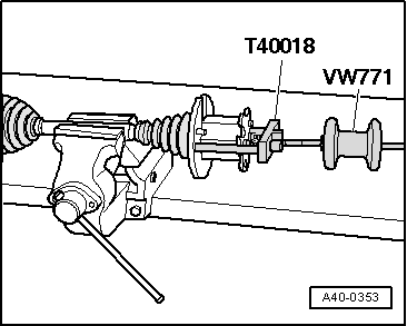
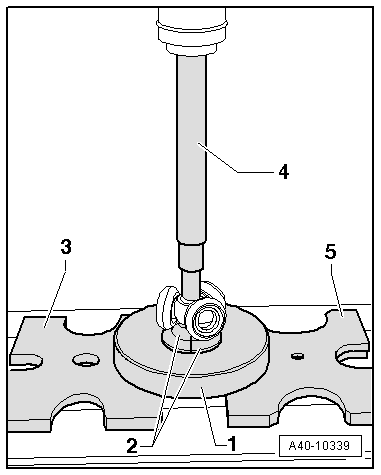
| –
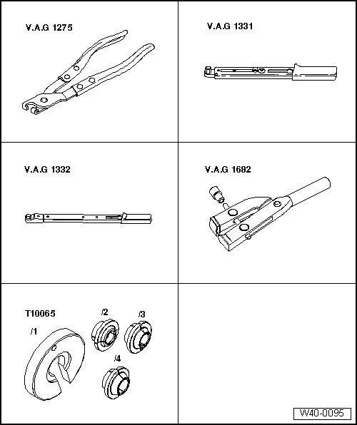
| Use the special tools shown in the illustration. |
| 1 - | Assembly tool -T10065/1- |
| 2 - | Assembly tool -T10065/5-, must make contact with base of triple roller spider |
| 3 - | Thrust plate -VW 401- |
| 4 - | Press tool -VW 408 A- |
| 5 - | Thrust plate -VW 402- |
| Assembly tool -T10065/5--2- must not rest on rollers (swivel the rollers aside if necessary). |
| –
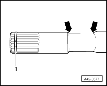
| Remove grease from shaft splines. |
| –
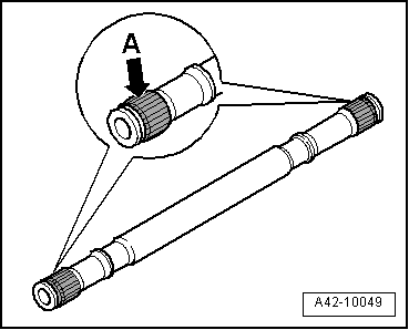
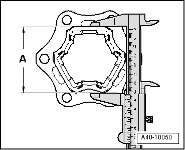
| Check rollers and roller races for wear. |
| –
| Clean drive shaft and housing. |
| Assembling triple roller joint AAR 2600 i or 3300 i |
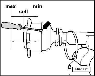
| –
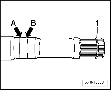
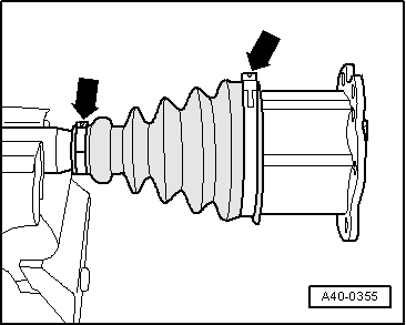
| Push on small hose clip with joint boot and bring boot into position on drive shaft (position varies depending on version). |
|
|
|


 Note
Note
 Caution