
A4 Mk3
| Exploded view of subframe, anti-roll bar, coupling rod - four-wheel drive vehicles |

| 1 - | Clamp |
| q | Is renewed together with rubber bush and anti-roll bar |
| q | Rubber bush and clamp must not be separated from anti-roll bar |
| 2 - | Bolt |
| q | 25 Nm +90° |
| q | Always renew if removed |
| q | Tighten evenly |
| 3 - | Bolt |
| q | 40 Nm +90° |
| q | Always renew if removed |
| q | Vehicle must be in unladen position when tightening → Chapter |
| 4 - | Bolt |
| q | 40 Nm +90° |
| q | Always renew if removed |
| q | Vehicle must be in unladen position when tightening → Chapter |
| 5 - | Coupling rod |
| q | Coupling rod is removed together with anti-roll bar |
| q | Removing and installing → Chapter |
| 6 - | Nut |
| q | Always renew if removed |
| 7 - | Anti-roll bar |
| q | Anti-roll bar is removed together with coupling rod |
| q | Removing and installing → Chapter |
| q | Rubber bush and clamp must not be separated from anti-roll bar |
| 8 - | Bolt |
| q | 70 Nm +180° |
| q | Always renew if removed |
| q | Vehicle must be in unladen position when tightening → Chapter |
| 9 - | Retaining bracket |
| 10 - | Bolt |
| q | 5 Nm |
| 11 - | Nut |
| q | Always renew if removed |
| 12 - | Upper transverse link |
| 13 - | Bolt |
| q | 115 Nm +90° |
| q | Always renew if removed |
| q | Bolts must not be loosened or tightened while springs are still installed. Before loosening or tightening bolts, slacken coil springs using spring compressor |
| 14 - | Rear left vehicle level sender -G76- |
| q | The same sender versions must be installed on both sides. |
| q | Complete with mounting parts |
| q | Lever of sender must face outwards |
| q | Renewing in vehicle → Chapter |
| q | Check basic adjustment of headlights if sender mountings are loosened → Rep. gr.94 |
| q | If, on vehicles with electronic damping control, the vehicle level sender has been removed and refitted or the linkage detached, the reference position must be re-adapted → Chapter. → Vehicle diagnostic, testing and information system VAS 5051 |
| q | If the reference position has been re-adapted on vehicles with lane departure warning, the lane departure warning control unit -J759- must be recalibrated → Chapter. |
| 15 - | Bolt |
| q | 9 Nm |
| 16 - | Bolt |
| q | 70 Nm +180° |
| q | Always renew if removed |
| q | Vehicle must be in unladen position when tightening → Chapter |
| 17 - | Lower transverse link |
| 18 - | Nut |
| q | Always renew if removed |
| 19 - | Bolt |
| q | 70 Nm +180° |
| q | Always renew if removed |
| q | Vehicle must be in unladen position when tightening → Chapter |
| 20 - | Track rod |
| q | Different versions (aluminium and steel); for correct version, refer to → Electronic parts catalogue |
| q | Mixed installation is not permissible |
| 21 - | Eccentric bolt |
| 22 - | Nut |
| q | 95 Nm |
| q | Always renew if removed |
| q | Vehicle must be in unladen position when tightening → Chapter |
| 23 - | Eccentric washer |
| 24 - | Support (left-side) |
| 25 - | Bolt |
| q | 55 Nm |
| 26 - | Bolt |
| q | 115 Nm +90° |
| q | Always renew if removed |
| q | Bolts must not be loosened or tightened while springs are still installed. Before loosening or tightening bolts, slacken coil springs using spring compressor |
| 27 - | Clip |
| q | Not fitted on all vehicles |
| 28 - | Stone deflector (left-side) |
| q | Not fitted on all vehicles |
| 29 - | Stone deflector (centre) |
| q | Not fitted on all vehicles |
| 30 - | Stone deflector (right-side) |
| q | Not fitted on all vehicles |
| 31 - | Bolt |
| q | Tightening torque → Rep. gr.39 |
| 32 - | Rear final drive |
| q | Removing and installing → Rep. gr.39 |
| 33 - | Cross member for differential |
| q | Removing and installing → Rep. gr.39 |
| q | Not fitted on vehicles with sport differential |
| 34 - | Bolt |
| q | Tightening torque → Rep. gr.39 |
| 35 - | Support (right-side) |
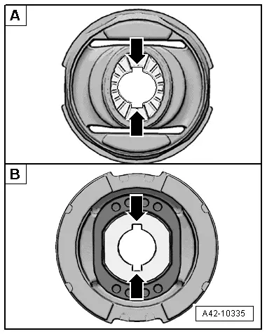
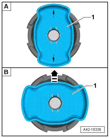
| 36 - | Bonded rubber bush (front) |
| q | For subframe mounting |
| q | Different types of bonded rubber bush (conventional or hydraulic) are fitted, depending on model → Anchor; for correct version refer to → Electronic parts catalogue |
| q | Oil stains on a hydraulic bonded rubber bush are a sign of wear |
| q | Renewing → Chapter |
| q | Always renew on both sides |
| 37 - | Spacer |
| q | Fitted on allroad |
| q | Note installation position: ribbed side faces body |
| 38 - | Subframe |
| q | Removing and installing subframe with attachments → Chapter |
| 39 - | Bonded rubber bush (front) |
| q | For rear final drive mounting |
| q | Renewing → Chapter |
| 40 - | Bonded rubber bush (rear) |
| q | For rear final drive mounting |
| q | Renewing → Chapter |
| 41 - | Bonded rubber bush (rear) |
| q | For subframe mounting |
| q | Different types of bonded rubber bush (conventional or hydraulic) are fitted, depending on model → Anchor; for correct version refer to → Electronic parts catalogue |
| q | Oil stains on a hydraulic bonded rubber bush are a sign of wear |
| q | Renewing → Chapter |
| q | Always renew on both sides |
| 42 - | Spacer |
| q | Fitted on allroad |
| q | Note installation position: ribbed side faces body |
| 43 - | Bonded rubber bush (rear) |
| q | For rear final drive mounting |
| q | Renewing → Chapter |
| 44 - | Bolt |
| q | Tightening torque → Rep. gr.39 |
|
|
|
|