audi Workshop Repair Guides

Audi Workshop Service and Repair Manuals

Renewing front bonded rubber bush for rear final drive - four-wheel drive vehicles > < Removing and installing subframe with attachments - four-wheel drive vehicles
Renewing conventional/hydraulic bonded rubber bushes for subframe - four-wheel drive vehicles
Special tools and workshop equipment required
   
t  Torque wrench -V.A.G 1332-
  W00-0428
t  Engine and gearbox jack -V.A.G 1383 A- with universal gearbox support -V.A.G 1359/2-
  W00-0120
t  Hydraulic press -VAS 6178-
  W00-1304
t  Foot pump -VAS 6179-
  W00-1305
t  Assembly tool -T10205-
  W00-10106
t  Assembly tool -T10263-
  W00-10648
t  Assembly tool -T40033-
  W00-10326
t  Assembly tool -T40185-
  W00-10687
t  Assembly tool -3346-
  W00-0207
t  Assembly tool -3301-
  Note
t  If a bonded rubber bush on one side is defective, the bush on the other side must be renewed at the same time. For correct version refer to → Electronic parts catalogue.
t  Also check the other bushes before renewing a defective bonded rubber bush.
t  
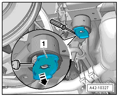
If cracks, oil stains or other damage is visible, these bonded rubber bushes must also be renewed.
t  Different versions of bonded rubber bush (conventional and hydraulic) are fitted, depending on the model → Anchor → Anchor. For correct version refer to → Electronic parts catalogue.
–  Raise vehicle on lifting platform.
–  Remove wheels.
–  Remove coil springs → Chapter.
  Note
t  
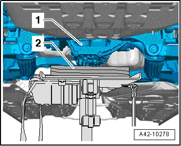
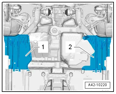
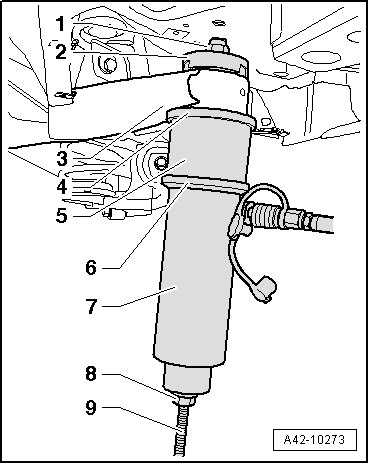
The front or rear part of the subframe is lowered in order to renew the bonded rubber bushes. The subframe does not have to be removed.
t  Lower the subframe at each end separately. This avoids the need for checking and adjusting wheel alignment.
t  
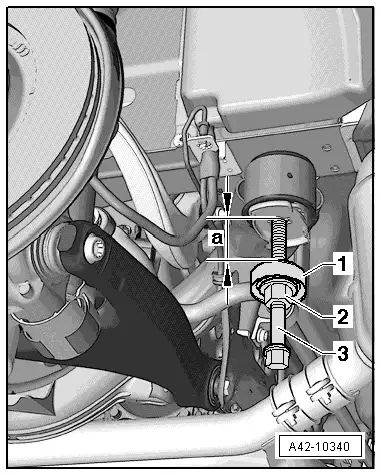
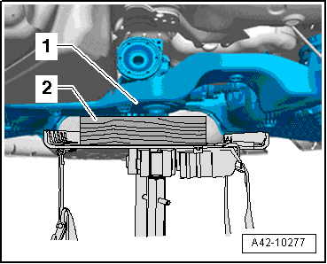
Do not lower the subframe more than 4 cm.
t  
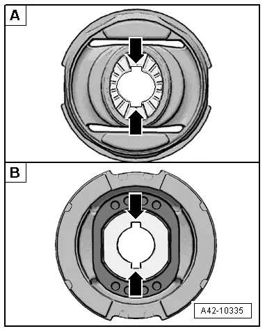
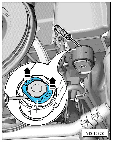
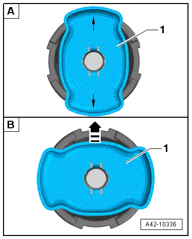
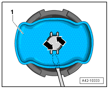
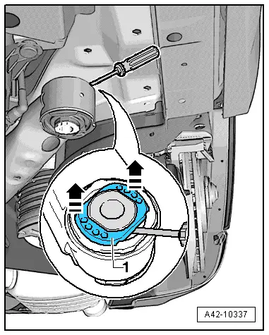
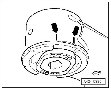
Mark the position of the bonded rubber bushes in relation to the subframe before removing them.
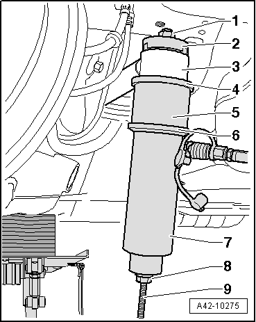
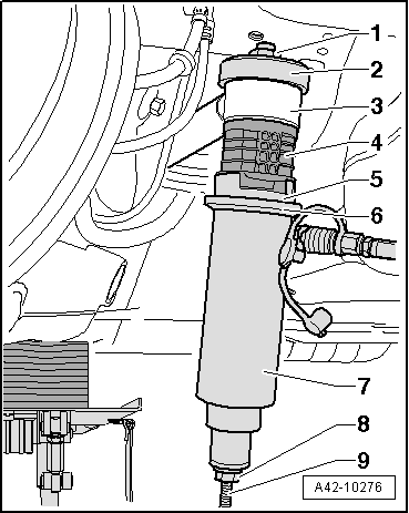
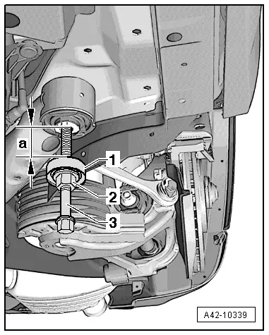
Renewing conventional or hydraulic bonded rubber bush (front)
  W00-0211
Applies to all versions:
–  Remove covers -1- and -2- → Rep. gr.66.
  A42-10220
–  Bring engine and gearbox jack with universal gearbox support -V.A.G 1359/2- into position under subframe -1-.
–  Insert a suitable block of wood -2- under subframe -1-.
  A42-10277
–  Remove bolts -1- and -2- on both sides.
–  Detach support -3- on both sides.
  A42-10221
–  Using assembly tool -3301- and nut -3346/3-, as shown in illustration, screw spindle -3346/2- approx. 1.5 cm into body on side opposite bonded rubber bush to be renewed.
1 - Assembly tool -3301-
2 - Nut -3346/3-
3 - Spindle -3346/2-
  Note
Screw nut -3346/3- onto spindle -3346/2- until distance -a- reaches 4 cm.
–  Lower subframe not more than 4 cm.
  A42-10339
Applies to hydraulic bonded rubber bush:
–  Lift out plastic insert -1-, as shown in illustration.
  A42-10337
Applies to all versions:
–  Mark installation position of bonded rubber bush in relation to subframe -arrows- using a felt-tip pen or similar.
The illustration shows a hydraulic bonded rubber bush. On conventional bonded rubber bushes, the recesses on the rubber beads are displaced by 90°.
  A42-10326
–  If necessary, unscrew small-diameter support -arrow- from hydraulic press -VAS 6178- and screw in support -T10205/13- in its place.
  A42-10109
–  Apply special tools to front bonded rubber bush as shown in illustration.
1 - Nut -T10263/5-
2 - Thrust piece -T40185/5- Recess faces towards bonded rubber bush.
3 - Subframe
4 - Support ring -T40185/6- Tapered end faces upwards and projections engage in recesses in bonded rubber bush.
5 - Tube -T40033/3-
6 - Support ring -T10205/4-
7 - Hydraulic press -VAS 6178-
8 - Nut -T10263/5-
9 - Spindle -T10263/4-. Pin on end of spindle faces downwards.
  WARNING
t  Hold hydraulic press -VAS 6178- securely during pressing operation.
t  The bonded rubber bush will come loose suddenly. Injuries can be caused if the tools and the bonded rubber bush are allowed to drop.
  A42-10273
Installation position of front bonded rubber bush
Grooves -arrows- are in line with direction of travel.
t  -A- Conventional bonded rubber bush
t  -B- Hydraulic bonded rubber bush
Grooves -arrows- are in line with direction of travel.
  A42-10335
–  Apply special tools to front bonded rubber bush as shown in illustration.
1 - Nut -T10263/5-
2 - Thrust piece -T40185/4-
3 - Subframe
4 - Conventional or hydraulic bonded rubber bush
5 - Thrust piece -T40185/3-
6 - Support ring -T10205/4-
7 - Hydraulic press -VAS 6178-
8 - Nut -T10263/5-
9 - Spindle -T10263/4-. Pin on end of spindle faces downwards.
–  Align bonded rubber bush with markings made earlier and press in at the correct position until collar is flush with subframe bushing. If necessary, slacken cylinder and then press home again. Ensure that the bonded rubber bush remains straight during the first stage of installation, otherwise the outer ring may be damaged.
  A42-10274
–  Ends of rubber bead on bonded rubber bush must align with markings -arrows- made earlier on subframe.
The illustration shows a hydraulic bonded rubber bush. On conventional bonded rubber bushes, the recesses on the rubber beads are displaced by 90°.
  Note
After renewing the bushes, make good any paint damage on the subframe with anti-corrosion coating, primer and black topcoat.
Remaining installation steps are carried out in reverse sequence.
Renewing conventional or hydraulic bonded rubber bush (rear)
Applies to all versions:
–  Unscrew nuts on both brackets for rear silencers as far as end of thread.
  A42-10326
–  Bring engine and gearbox jack with universal gearbox support -V.A.G 1359/2- into position under subframe -1-.
–  Insert a suitable block of wood -2- under subframe -1-.
  A42-10278
–  Remove rear subframe bolts → Item.
–  Using assembly tool -3301- and nut -3346/3-, as shown in illustration, screw spindle -3346/2- approx. 1.5 cm into body on side opposite bonded rubber bush to be renewed.
1 - Assembly tool -3301-
2 - Nut -3346/3-
3 - Spindle -3346/2-
  Note
Screw nut -3346/3- onto spindle -3346/2- until distance -a- reaches 4 cm.
–  Lower subframe not more than 4 cm.
  A42-10340
Applies to hydraulic bonded rubber bush:
–  Carefully lever locating element -1- off hydraulic bonded rubber bush in several stages on alternate sides by applying a screwdriver or similar tool in area of retaining lugs.
  A42-10327
–  Lift out plastic insert -1-, as shown in illustration.
  A42-10328
Applies to all versions:
–  Mark installation position of bonded rubber bush in relation to subframe -arrows- using a felt-tip pen or similar.
The illustration shows a hydraulic bonded rubber bush. On conventional bonded rubber bushes, the recesses on the rubber beads are displaced by 90°.
  A42-10326
–  If necessary, unscrew small-diameter support -arrow- from hydraulic press -VAS 6178- and screw in support -T10205/13- in its place.
  A42-10109
–  Apply special tools to front bonded rubber bush as shown in illustration.
1 - Nut -T10263/5-
2 - Thrust piece -T40185/5- Recess faces towards bonded rubber bush.
3 - Subframe
4 - Support ring -T40185/6- Tapered end faces upwards and projections engage in recesses in bonded rubber bush.
5 - Tube -T40033/3-
6 - Support ring -T10205/4-
7 - Hydraulic press -VAS 6178-
8 - Nut -T10263/5-
9 - Spindle -T10263/4-. Pin on end of spindle faces downwards.
  WARNING
t  Hold hydraulic press -VAS 6178- securely during pressing operation.
t  The bonded rubber bush will come loose suddenly. Injuries can be caused if the tools and the bonded rubber bush are allowed to drop.
  A42-10275
Installation position of rear bonded rubber bush
t  -A- Conventional bonded rubber bush (arrows are in line with direction of travel)
t  -B- Hydraulic bonded rubber bush (locating element -1- is perpendicular to direction of travel, -arrow- is pointing in direction of travel)
  A42-10336
Applies to hydraulic bonded rubber bush:
Before installing hydraulic bonded rubber bush (rear), carefully lever locating element -1- off hydraulic bonded rubber bush in several stages on alternate sides by applying a screwdriver or similar tool in area of retaining lugs -arrows-.
  A42-10333
Applies to all versions:
–  Apply special tools to rear bonded rubber bush as shown in illustration.
1 - Nut -T10263/5-
2 - Thrust piece -T40185/4-
3 - Subframe
4 - Conventional or hydraulic bonded rubber bush
5 - Thrust piece -T40185/3-
6 - Support ring -T10205/4-
7 - Hydraulic press -VAS 6178-
8 - Nut -T10263/5-
9 - Spindle -T10263/4-. Pin on end of spindle faces downwards.
–  Align bonded rubber bush with markings made earlier and press in at the correct position until collar is flush with subframe bushing. If necessary, slacken cylinder and then press home again. Ensure that the bonded rubber bush remains straight during the first stage of installation, otherwise the outer ring may be damaged.
  A42-10276
–  Ends of rubber bead on bonded rubber bush must align with markings -arrows- made earlier on subframe.
The illustration shows a hydraulic bonded rubber bush. On conventional bonded rubber bushes, the recesses on the rubber beads are displaced by 90°.
  Note
After renewing the bushes, make good any paint damage on the subframe with anti-corrosion coating, primer and black topcoat.
–  Fit locating element on hydraulic bonded rubber bush.
Remaining installation steps are carried out in reverse sequence.
  A42-10326

Renewing front bonded rubber bush for rear final drive - four-wheel drive vehicles > < Removing and installing subframe with attachments - four-wheel drive vehicles