
A4 Mk3
|
 Note
Note| t | Renew seals. |
| t | Do not re-use hydraulic fluid which has been drained off. |
| t | Use only hydraulic fluid. |

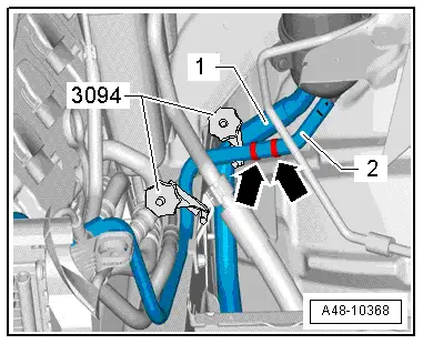
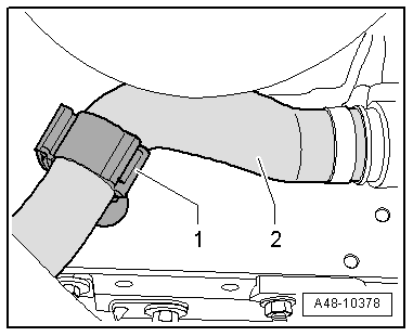
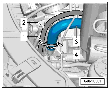
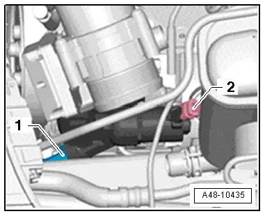
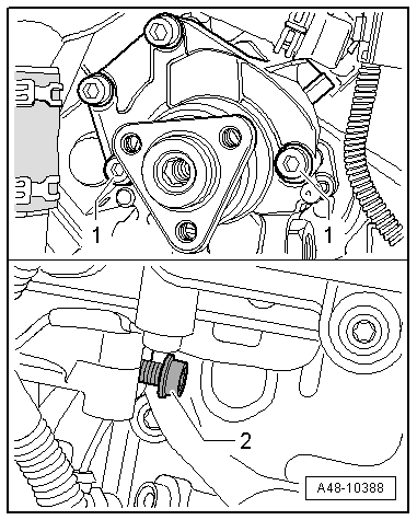
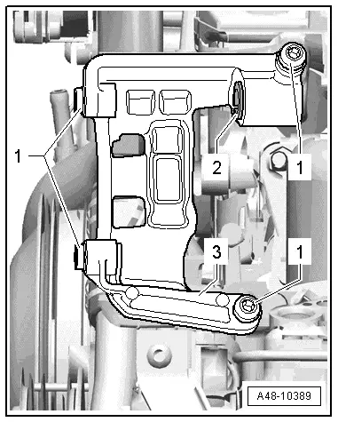
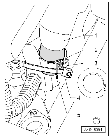
| 1 - | Bracket |
| 2 - | Sleeve |
| q | Sleeve must be driven back slightly to install power steering pump |
| 3 - | Bolt |
| q | 20 Nm |
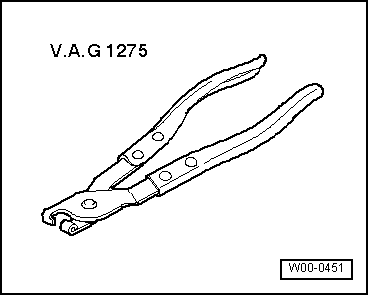
| 4 - | Hose clip |
| q | Tighten using hose clip pliers -V.A.G 1275- |
| q | Always renew if removed |
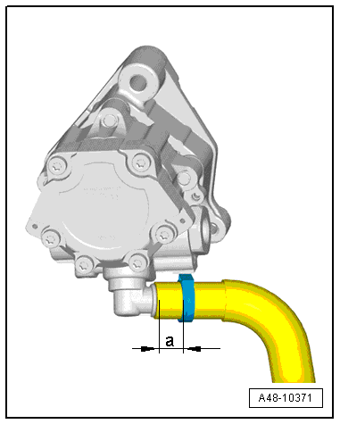
| 5 - | Suction hose |
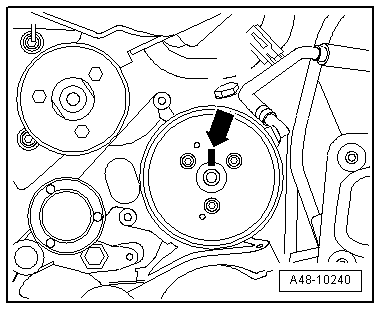
| q | Marking „P“-arrow- on suction hose must be in line with seam -arrow- on power steering pump. |
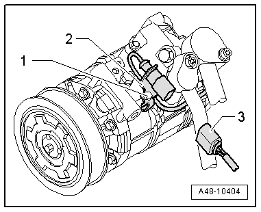
| 6 - | Regulating valve for power steering pump -(V119)- |
| q | Power steering pump and regulating valve are combined as one component and can only be renewed together |
| 7 - | Steering hydraulics pump -V119- |
| q | With regulating valve for power steering pump -(V119)- |
| q | Power steering pump and regulating valve → Item are combined as one component and can only be renewed together |
| q | For correct version refer to → Electronic parts catalogue |
| q | Fill with hydraulic fluid before installing |
| q | Checking delivery pressure → Chapter |
| q | Bleeding steering system → Chapter |
| q | Checking hydraulic fluid level → Chapter |
| q | Checking steering system for leaks → Chapter |
| 8 - | Seal |
| q | Always renew if removed |
| 9 - | Union nut |
| q | 38 Nm |
| 10 - | Pressure line |
 Caution
|
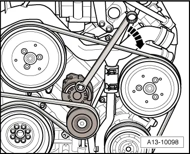
| q | Note correct position: Angle between pipe connection and shaft of power steering pump is approx. 59° |
| q | Also secured to A/C compressor, depending on version |
| 11 - | Bolt |
| q | 22 Nm |
| 12 - | Belt pulley |
| 13 - | Bolt |
| q | 20 Nm |
| q | For securing bracket to engine |
| q | Note different lengths of bolts |
| 14 - | Bolt |
| q | 20 Nm |
| q | For securing bracket to engine |
| q | Note different lengths of bolts |
| 15 - | Bolt |
| q | 20 Nm |
| q | For securing power steering pump to bracket |
| 16 - | Bolt |
| q | 20 Nm |
| q | For securing bracket to engine |
|
|
|
|
|
|
|
|
|
|
|
|
|
|
|
|
|
|
|
Note
|
|
|
|
Note
|
|
|
|
|
|
|
|
|
|
Note
|
|
|
|
|
|
Note
|
|
|
|
|
|
Note
|
|
|
|
|
|
|
|
|
|
|
|
|
|
Note
|
|