
A4 Mk3
 Note
Note
|
|
|
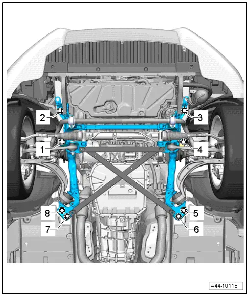
| – | Slacken bolts -1- to -8-. |
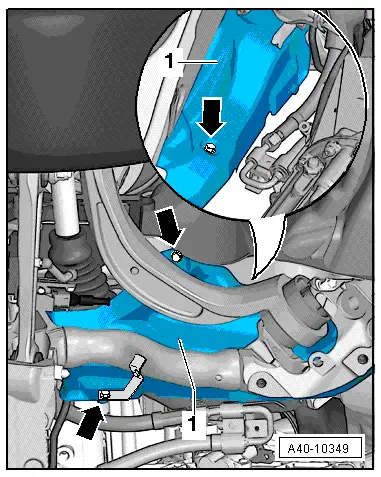
| The following steps are required in order to slacken bolt -1- (depending on engine version): |
| t | Detach shield for drive shaft (if fitted). |
| t | Remove one clip from wheel housing liner. |
| t | Swivel wheel housing liner aside slightly. |
Note
|
|
|
 WARNING
| – | Tighten bolts -2- and -3- to specified torque. |
| – | Screw in and tighten new bolts -1- and -4- in turn → Chapter. |
| – | Screw in and tighten new bolts -2- and -3- in turn → Chapter. |
| – | Screw in and tighten new bolts -8- and -5- in turn → Chapter. |
| – | Screw in and tighten new bolts -7- and -6- in turn → Chapter. |
|