| When the hazard warning lights are off, the indicator lamp for hazard warning light -K6- is illuminated (with dimming) by the onboard supply control unit -J519- by way of a PWM signal, provided terminal 58st is active (see section 5.3.2). |
| In this case, the dimming function is used for the purposes of switch illumination. The dimming value is calculated by the onboard supply control unit -J519- from the terminal 58st dimming value by way of an internal algorithm. |
| When the hazard warning lights are on, the indicator lamp for hazard warning light -K6- is activated by the onboard supply control unit -J519- in synchronism with the hazard warning lights. The indicator lamp is activated with a 100% PWM signal during the on-phase, and with a PWM signal of 0% during the off-phase. |
| The hazard warning lights are activated as follows: |
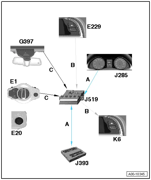
| The status of the hazard warning lights button -E229- is evaluated by the onboard supply control unit -J519-. |
| If the button is detected as pressed, the information is sent over the CAN bus to the convenience system central control unit -J393-, which serves as the flash master. It then sends the information specifying the frequency at which the indicator lamp for hazard warning light -K6- is to be activated over the CAN bus to the onboard supply control unit -J519-. |
| In case of emergency braking, or in the event of an accident involving triggering of the airbags, the hazard warning lights are automatically switched on by the convenience system central control unit -J393- and the flash frequency information is sent to the onboard supply control unit -J519-. |
|
|
|