audi Workshop Repair Guides

Audi Workshop Service and Repair Manuals

Detaching refrigerant lines from air conditioner compressor/attaching > < Notes on general repairs
Removing and installing heat exchanger
  Note
   
On account of the restricted space available, a factory-fitted heat exchanger can not be re-installed, or not with the necessary degree of safety, with the dash panel (and the air conditioning unit) fitted due to the clips -B- and -C-. If the original factory-fitted heat exchanger is to be re-installed, the dash panel and the air duct to the „Defrost“ vent must be removed. Then attach the O-rings moistened with a small quantity of coolant (as described for installation of the replacement heat exchanger) to the coolant pipes -D- and -E- and press the coolant pipes -D- and -E- (with the O-rings) from above into the connections at the heat exchanger -A-. Hold the coolant pipes -D- and -E- in the heat exchanger and fit the clips -B- and -C-. Further installation is then to be performed as described for the replacement heat exchanger.
Removing
–  Preparation for heat exchanger removal → Chapter.
–  Dissipate the pressure in the coolant circuit by opening the cap at the coolant expansion tank → Engine, mechanics; Rep. gr.13.
  A87-10517
–  Mark the arrangement of the coolant hoses -A- (supply from cylinder head) and -B- (return to coolant pump).
  Note
t  The heat exchanger is designed for a certain coolant flow direction. The coolant hoses must therefore be connected on the correct sides.
t  Bleeding coolant circuit → Engine, mechanics; Rep. gr.13.
–  Use hose clamps to pinch off the coolant hoses -A- and -B-.
–  Cover the area beneath the connections for the coolant hoses -A- and -B- in the plenum chamber with absorbent paper for example.
–  Detach the coolant hoses -A- and -B- from the connections to the heat exchanger of the air conditioning unit → Engine, mechanics; Rep. gr.13.
  A87-10515
–  Attach a section of tubing (-A- and -C-) to each of the two connections to the heat exchanger.
–  Place a vessel -B- beneath the other end of the hose -C-.
–  Use a compressed air gun -D- to carefully blow the coolant via the hose -A- out of the heat exchanger (into the vessel -B-).
  A87-10516
–  Detach the clips -B- and -C- from the connections at the heat exchanger -A-.
–  Unfasten the two coolant pipes -D- and -E- from the connections of the heat exchanger -A-.
–  Remove the heat exchanger -A- in arrow direction -arrow-.
  Note
  A87-10517
The upper illustration shows a heat exchanger with connections as fitted at the factory. If the heat exchanger has already been replaced, the two coolant pipes in the replacement heat exchanger are held in position in the heat exchanger with a holder -A-. Screw out the bolt -B- on this heat exchanger. Then screw home a longer bolt -C- (with M5 thread) as shown and use this bolt to unfasten the holder -A- from the connection.
Installing
Install in reverse order, paying attention to the following:
  A87-10518
–  Affix the foam seals -A- to -D- supplied to the heat exchanger to be fitted in line with the air conditioner and vehicle version.
1 - Heat exchanger for left or right-hand drive vehicle with air conditioner of „Basic“ type
2 - Heat exchanger for left-hand drive vehicle with air conditioner of „Deluxe“ type
3 - Heat exchanger for right-hand drive vehicle with air conditioner of „Deluxe“ type
–  Check the seals attached to the heat exchanger. Only install a heat exchanger if the seals are in perfect condition and firmly affixed.
  Note
t  Different temperature settings are possible on vehicles with an air conditioner of the „Deluxe“ type for the left and right side and the rear area. The seals -C- and -D- separate the air ducts in the air conditioning unit for these areas → Chapter „Air intake, air outlet and air routing in air conditioning unit“.
t  The heat exchanger is provided with a coloured marking to which the seal -C- is to be bonded. Bond the seal -D- in central position on the heat exchanger as shown.
t  There are different lengths of seal -C- (a short version as shown or a long version which extends around the entire heat exchanger). If the scope of delivery of the heat exchanger includes a long sealing strip -C-, this is to be bonded on all round the heat exchanger.
t  The seal may curl up on insertion if not correctly bonded on.
t  If the seal is damaged or has not been fitted properly, cold air can flow past the heat exchanger. On vehicles with an air conditioner of the „Deluxe“ type, proper separation between the different areas may then not be possible.
  A87-10519
–  With the heat exchanger -A- removed, check the air conditioning unit and the evaporator -F- for contamination (by way of the slot for the heat exchanger).
–  Remove any dirt or remnants of escaped coolant from the air conditioning unit (e.g. after removing a leaking heat exchanger).
  A87-10517
–  Check the two connections -A- and -B- of the heat exchanger -C- for damage or contamination.
–  Apply a small quantity of silicone grease to the two connections -A- and -B- of the heat exchanger -C-.
  Note
Replacement silicone grease can be obtained for example under part number G 000 405 A2 → Electronic parts catalogue.
  A87-10625
–  Moisten the new seals -D- (included in the scope of delivery of the heat exchanger) with a small quantity of coolant (or lubricate slightly with silicone grease).
–  Attach the new seals -D- to the two coolant pipes -E- and -F- to the heat exchanger.
  A87-10520
–  Slide the heat exchanger -A- into the air conditioning unit.
–  Support the heat exchanger -A- for example with a plastic wedge -B- at the transmission tunnel -C- to stop it slipping down when pressing in the coolant pipes.
  A87-10626
–  Screw home a longer bolt -G- (with M5 thread) in the holder -C- as shown.
–  Insert the two coolant pipes -E- and -F- with the corresponding seal -D- in the heat exchanger connections at the connecting flange -H- and press home.
  Caution
Leakage at heat exchanger.
Squashed O-rings and coolant pipes / clips not fitted straight or not fully attached will lead to leakage.
  Note
  A87-10520
Take care to keep the coolant pipes -D- and -E- straight on pressing into the connections at the heat exchanger.
–  Check the position of the seals -C- between the coolant pipes -D- and -E- and the connections in the connecting flange -B- of the heat exchanger -A-.
  Caution
Leakage will occur if seals -C- are fitted incorrectly or crushed.
In both connections, the seals -C- must be fully inserted with the coolant pipes -D- and -E- in the connections in the connecting flange -B-.
  A87-10627
–  Attach the two coolant pipes -E- and -F- with the holder -C- to the connecting flange of the heat exchanger -H-.
  Note
The bolt -G- is an assembly aid and is to be removed after installing the holder.
–  Insert the bolt -A- with the packing plate -B- and tighten the bolt -A-.
Tightening torque of bolt -A- 2.5 Nm.
–  Remove the bolt -G-.
  A87-10520
–  Check that the socket -H- is correctly positioned in the back wall of the plenum chamber.
–  Properly connect the coolant hoses to the heat exchanger, paying attention to the markings.
A - Supply from cylinder head
B - Return to coolant pump
–  Attach the coolant hose -A- to the coolant pipe to the heat exchanger (heed the marking) and secure it with the clip -D-.
–  Slip the coolant hose to the heat exchanger -B- over the coolant pipe -F- such that the bleed hole -G- is not sealed off.
–  Detach the hose clamp from the coolant hose -A-.
–  Replenish the coolant in the coolant expansion tank → Engine, mechanics; Rep. gr.19.
–  Using the hand pump of the cooling system tester -V.A.G 1274/- for example, carefully force coolant out of the coolant expansion tank into the heat exchanger.
–  As soon as the coolant emerges from the bleed hole -G-, attach the coolant hose -B- in line with the mark made to the coolant pipe -F-.
–  Secure the coolant hose -B- with the clip -E- at the marked location.
–  Detach the hose clamp from the coolant hose -B-.
–  If necessary, pour further coolant into the coolant expansion tank → Engine, mechanics; Rep. gr.19.
  Note
This procedure completely bleeds the cooling system. If there is still air in the cooling system for some other reason, bleed the cooling system again if necessary after fitting all the components removed → Engine, mechanics; Rep. gr.19.
Check the connections at the heat exchanger for leaks as follows:
–  Use the hand pump of the cooling system tester -V.A.G 1274/- for example to carefully increase the pressure in the coolant circuit.
  A87-10515
–  Check the coolant circuit for leaks, paying particular attention to the connection between the coolant pipes and the heat exchanger → Engine, mechanics; Rep. gr.19.
  Note
t  When bleeding the coolant circuit, take special care to ensure complete bleeding of the heat exchanger. If air bubbles remain in the heat exchanger, complaints may be received about a lack of heat output in winter or differences in the temperature of the air flowing out of the vents with the same setting in control mode → Chapter.
t  Depending on the vehicle equipment and the engine, the coolant hoses may be provided with thermal insulation. This must not be damaged and must be re-attached following installation.
–  Re-install all the components removed in the reverse order → Chapter (preparation for removal of heat exchanger).
Vehicles with a high-voltage system (hybrid vehicles)
–  Attach the high-voltage cables to the electrical air conditioner compressor -V470- and from the drive battery -A2- to the power and control electronics for electric drive -JX1- → Electrical system; Rep. gr.93.
–  Fit the scuttle panel trim -C- → General body repairs, exterior; Rep. gr.50
  A87-10518
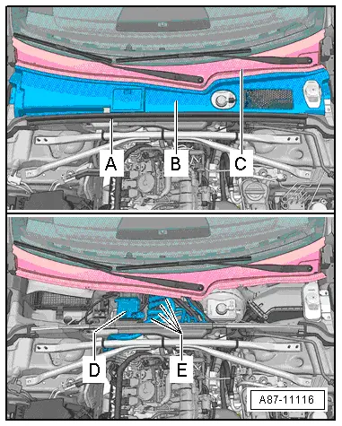
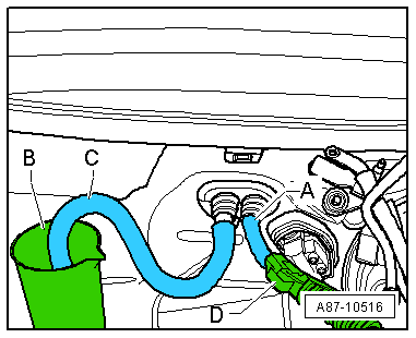
–  Check for proper installation of the power and control electronics for electric drive -JX1--D- and the corresponding wiring -D- → Electrical system; Rep. gr.93
–  Re-establish the high-voltage system supply → Electrical system; Rep. gr.93
Re-activation of high-voltage system
  DANGER!
Potentially fatal high voltage
Risk of fatal or serious injury from electric shocks
t  High voltage at high-voltage system!
t  For safety reasons, work on the high-voltage system is not to be performed by persons wearing electronic/medical life and health-preserving devices in or on the body. Life and health-preserving devices include internal painkiller pumps, implanted defibrillators, pacemakers, insulin pumps and hearing aids.
t  The high-voltage system is only to be re-activated by an appropriately qualified person (Audi high-voltage engineer).
t  Re-activation is to be determined solely by way of the Vehicle diagnostic tester employing the „Guided fault-finding“ routine.
t  The qualified person (Audi high-voltage engineer) re-activates the vehicle.
t  The qualified person (Audi high-voltage engineer) attaches signs to mark the vehicle accordingly.
  Note
t  High-voltage system re-activation:
t  Connect the vehicle diagnostic tester
t  Select Guided fault-finding mode
t  Use the Go to key to consecutively select the following menu items
t  Function/component list
t  Body
t  Electrical system
t  Systems with self-diagnosis capability
t  8C - Hybrid battery management -J840
t  8C - Hybrid battery management, functions
t  51 - Re-activation of high-voltage system (Rep. Gr. 93)
Vehicles with no high-voltage system
–  Re-connect the earth connection of the battery -A-, paying attention to the notes on battery connection → Electrical system; Rep. gr.27.
All vehicles
–  Switch on the ignition.
–  Perform air conditioner basic setting and final control diagnosis → "Guided fault-finding" function of vehicle diagnostic, testing and information system VAS 5051.
  Note
t  The control motors on this vehicle are equipped with electronics. A new control motor only learns its position at the air conditioning unit in the course of basic setting and can then be actuated by the air conditioner operating and display unit, Climatronic control unit -J255- (all control motors are identical at present) → "Guided fault-finding" function of vehicle diagnostic, testing and information system VAS 5051.
t  During basic setting, control motor assignment and adaption are implemented on the basis of the arrangement in the series connection of the wiring. If the sequence is not as specified, the matching of the control motors and thus flap control will not be correct → Chapter (block diagram of air conditioner control motors).
–  Switch on the ignition.
–  Interrogate the event recorder of the air conditioner operating and display unit, Climatronic control unit -J255- and erase any faults displayed → "Guided fault-finding" function of vehicle diagnostic, testing and information system VAS 5051.
–  By making different settings on the air conditioner operating and display unit, Climatronic control unit -J255-, direct the air to the various vents and check whether the flow of air out of the vent actually changes in line with the setting.
  A87-11116

Detaching refrigerant lines from air conditioner compressor/attaching > < Notes on general repairs