audi Workshop Repair Guides

Audi Workshop Service and Repair Manuals

Block diagram of auxiliary heater actuation with remote control > < Block diagram of auxiliary heater
Incorporation of auxiliary heater into vehicle electrical system
  Note
For incorporation of auxiliary heater into vehicle electrical system, refer to → Current flow diagrams, Electrical fault finding and Fitting locations.
   
Assignment of contacts in the 2-pin connector (wire from heater to circulation pump -V55-)
1 - Circulation pump -V55- actuation
2 - Circulation pump -V55- earth connection
  N82-10143
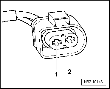
Assignment of contacts in the 2-pin connector (wire on vehicle end to heater)
1 - Power supply, terminal 30
2 - Earth connection
  Note
As of 10.2010 auxiliary heaters with part number 4xx xxx  xxx are gradually to be introduced. Service installation of this version of the auxiliary heater is also possible in vehicles originally fitted with an auxiliary heater with part number 8R0 xxx xxx or 8K0 xxx xxx. As however there are differences between certain components of the various auxiliary heater versions (e.g. the 2-pin connector for the power supply to the auxiliary heater control unit -J364-), attention must be paid to correct assignment when replacing individual components of the auxiliary heater → Electronic parts catalogue.
  N82-10143
Assignment of contacts in the 6-pin connector (wire on vehicle end to heater)
1 - Signal wire to data bus (high-speed CAN bus).
2 - Signal wire to data bus (low-speed CAN bus).
3 - Heater coolant shut-off valve -N279- actuation
4 - Actuation of metering pump -V54-
5 - Not used at present.
6 - Signal wire from auxiliary heating radio controlled receiver -R64-
  A82-10132

Block diagram of auxiliary heater actuation with remote control > < Block diagram of auxiliary heater