
A5
 Note
Note
|
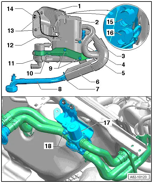
| 1 - | Holder |
| 2 - | Auxiliary heater |
| q | Removing and installing → Chapter |
| q | Different versions; the Audi Q5 is not to be fitted with auxiliary heaters with part number 8K0.xxx.xxx for example. In addition, the versions depend on the production period and the type of fuel (there are different settings for certain functions for petrol and diesel) → Chapter and → Electronic parts catalogue |
Note| t | As of Model Year 2010 a start/stop system will be available as an optional extra for this vehicle in conjunction with certain engines. On these vehicles, pay attention to the correct version of the air conditioner operating and display unit, Climatronic control unit -J255- and of the auxiliary heater → Electronic parts catalogue and → "Guided fault-finding" function of vehicle diagnostic, testing and information system VAS 5051. |
| t | Vehicles with a start/stop system are not to be fitted with auxiliary heaters with part number 8K0 xxx xxx → Electronic parts catalogue and → "Guided fault-finding" function of vehicle diagnostic, testing and information system VAS 5051. |
| 3 - | Clamp |
| q | Bolt tightening torque 6 Nm |
| q | For corrugated pipe to exhaust silencer |
| 4 - | Bolt |
| q | Tightening torque 6 Nm |
| q | For the holder of the intake air noise insulation |
| q | Self-tapping bolt with coating, replace |
| 5 - | Intake air noise insulation |
| q | Removing and installing → Chapter |
Note| t | Secure the intake hose with a clamp to stop it slipping off the air intake connection of the auxiliary heater. |
| t | If applicable, additionally attach the intake air noise insulation with cable ties to the auxiliary heater holder. |
| 6 - | Exhaust silencer |
| q | Removing and installing → Chapter |
Note| Depending on the design of the auxiliary heater and the vehicle equipment spec, there may be a thermal insulator on the exhaust pipe fitted between the auxiliary heater and the exhaust silencer (to protect the surrounding components). |
| 7 - | Clamp |
| q | Tightening torque 6 Nm |
| q | For exhaust pipe |
| 8 - | Exhaust pipe |
Note| t | The flow of exhaust gas out of the exhaust pipe must not be obstructed. |
| t | After working on the auxiliary/supplementary heater or the noise insulation, check the mouth of the exhaust pipe. This must be fitted at right angles to the noise encapsulation where it passes through the noise encapsulation → Chapter. |
| 9 - | Bolt |
| q | Tightening torque 6 Nm |
| q | For holder of circulation pump -V55- |
| q | Self-tapping bolt with coating, replace |
| q | A rubber grommet is fitted as isolator between the bolt and holder → Anchor |
| 10 - | Bolt |
| q | Tightening torque 3.5 Nm |
| q | For circulation pump -V55- retaining clip |
| 11 - | Circulation pump -V55- |
| q | Removing and installing → Chapter |
| 12 - | Connection for fuel pipe |
| 13 - | Nut |
| q | 2x |
| q | Tightening torque 20 Nm |
| q | Heed tightening sequence → Chapter „Installing auxiliary heater“ |
| 14 - | Bolt |
| q | Tightening torque 20 Nm |
| q | Heed tightening sequence → Chapter „Installing auxiliary heater“ |
| 15 - | Control line connector |
| q | Attached to the holder with a clip |
| 16 - | Power supply connector |
| q | Attached to the holder with a clip |
| q | Different connector versions depending on the model |
Note| As of 10.2010 auxiliary heaters with part number 4xx xxx xxx are gradually to be introduced. Service installation of this version of the auxiliary heater is also possible in vehicles originally fitted with an auxiliary heater with part number 8R0 xxx xxx or 8K0 xxx xxx. As however there are differences between certain components of the various auxiliary heater versions (e.g. the 2-pin connector for the power supply to the auxiliary heater control unit -J364-), attention must be paid to correct assignment when replacing individual components of the auxiliary heater → Electronic parts catalogue. |
| 17 - | Heater coolant shut-off valve -N279- |
| q | Fitted in the plenum chamber on the right. |
| q | Removing and installing → Chapter |
| q | Operation → Chapter |
| q | Different versions (for Audi A5 Coupé, Audi A4 and Audi Q5); pay attention to correct assignment → Electronic parts catalogue. |
Note| t | To stop the flow of coolant from the cylinder head being completely interrupted with the engine running and -N279- actuated, certain vehicles are fitted with a non-return valve in the coolant circuit → Chapter |
| t | On the Audi Q5, actuation of -N279- is only permissible up to a certain engine speed (currently up to approx. 1200 rpm). Attention is therefore to be paid to the correct version, encoding and adaption of the auxiliary heater → Vehicle diagnostic, testing and information systemVAS 5051/, “Guided fault-finding function”. |
| 18 - | Bolt |
| q | Tightening torque 8 Nm |
| q | For heater coolant shut-off valve -N279- |
Note
|
|
|
|
Note| t | The following illustration shows the auxiliary heater with the holder “2” which was fitted at the start of production in Model Year 2009. |
| t | Refer to view “2” for all components not mentioned. |
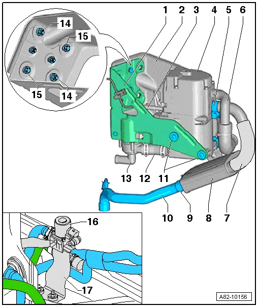
| 1 - | Holder 1 |
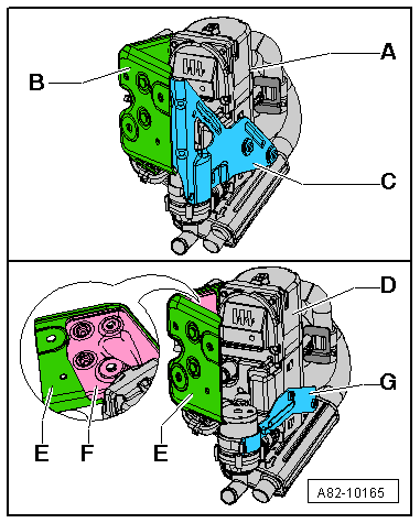
| q | Holders “1” and “2” are bolted together → Anchor |
| q | Different versions depending on the production period. |
| 2 - | Holder “2” |
| q | Holders “1” and “2” are bolted together → Anchor |
| q | Different versions depending on the production period. |
| 3 - | Connection for fuel pipe |
| 4 - | Auxiliary heater |
| q | Removing and installing → Chapter |
| q | Different versions; the Audi Q5 is not to be fitted with auxiliary heaters with part number 8K0.xxx.xxx for example. In addition, the auxiliary heater version depends on the production period and the type of fuel (there are different settings for certain functions for petrol and diesel) → Chapter and → Electronic parts catalogue |
| 5 - | Clamp |
| q | Bolt tightening torque 6 Nm |
| q | For corrugated pipe to exhaust silencer |
| 6 - | Intake air noise insulation |
| q | Removing and installing → Chapter |
| q | Attached with retainers and cable ties to holder “2”. |
Note| t | Secure the intake hose with a clamp to stop it slipping off the air intake connection of the auxiliary heater. |
| t | If applicable, additionally attach the intake air noise insulation with cable ties to the auxiliary heater holder. |
| 7 - | Thermal insulation at corrugated pipe to exhaust silencer |
| q | Not fitted with all versions → Electronic parts catalogue |
| 8 - | Exhaust silencer |
| q | With corrugated pipe |
| q | Removing and installing → Chapter |
Note| Depending on the version of the auxiliary heater and the vehicle equipment, the exhaust pipe fitted between the auxiliary heater and the exhaust silencer may be provided with thermal insulation (to protect the surrounding components). |
| 9 - | Clamp |
| q | Tightening torque 6 Nm |
| q | For exhaust pipe |
| 10 - | Exhaust pipe |
Note| t | The flow of exhaust gas out of the exhaust pipe must not be obstructed. |
| t | After working on the auxiliary/supplementary heater or the noise insulation, check the mouth of the exhaust pipe. This must be fitted at right angles to the noise encapsulation where it passes through the noise encapsulation → Chapter. |
| 11 - | Bolt |
| q | Tightening torque 6 Nm |
| q | For holder “1” |
| q | Self-tapping bolt with coating, replace |
| q | A rubber grommet is fitted as isolator between the bolt and holder → Anchor |
| 12 - | Coolant hose |
| q | Between circulation pump -V55- and auxiliary heater |
| 13 - | Circulation pump -V55- |
| q | Removing and installing → Chapter |
| 14 - | Nut |
| q | 2x |
| q | Tightening torque 20 Nm |
| q | Heed tightening sequence → Chapter „Installing auxiliary heater“ |
| 15 - | Bolt |
| q | 2x |
| q | Tightening torque 20 Nm |
| q | Heed tightening sequence → Chapter „Installing auxiliary heater“ |
| 16 - | Heater coolant shut-off valve -N279- |
| q | Fitted in the plenum chamber on the right |
| q | Removing and installing → Chapter |
| q | Operation → Chapter |
| q | Different versions for Audi A5 Coupé, Audi A4 and Audi Q5; pay attention to correct assignment → Electronic parts catalogue. |
Note| t | To stop the flow of coolant from the cylinder head being completely interrupted with the engine running and -N279- actuated, certain vehicles are fitted with a non-return valve in the coolant circuit → Chapter |
| t | On the Audi Q5, actuation of -N279- is only permissible up to a certain engine speed (currently up to approx. 1200 rpm). Attention is therefore to be paid to the correct version, encoding and adaption of the auxiliary heater → Vehicle diagnostic, testing and information systemVAS 5051/, “Guided fault-finding function”. |
| 17 - | Holder |
| q | For heater coolant shut-off valve -N279- |
| q | Tightening torques of bolts/nuts (for attaching heater coolant shut-off valve -N279- to holder and holder to vehicle) 8 Nm in each case |
Note
|

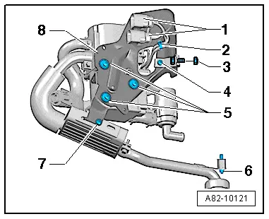
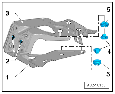
| 1 - | Control line connector |
| q | Attached to the holder “2” with a clip |
| 2 - | Power supply connector |
| q | Attached to the holder “2” with a clip |
| 3 - | Bolt |
| q | Tightening torque 6 Nm |
| q | For holder of circulation pump -V55- |
| q | Self-tapping bolt with coating, replace |
| q | A rubber grommet is fitted as isolator between the bolt and holder → Anchor |
| 4 - | Bolt |
| q | Tightening torque 6 Nm |
| q | For exhaust silencer |
| 5 - | Circulation pump -V55- |
| q | Removing and installing → Chapter |
| 6 - | Bolt |
| q | Tightening torque 3.5 Nm |
| q | For circulation pump -V55- retaining clip |
| 7 - | Retaining clip |
| q | For circulation pump -V55- |
| 8 - | Holder “2” |
| q | Holders “1” and “2” are bolted together → Anchor |
| 9 - | Bonded rubber bush |
Note
|
|