audi Workshop Repair Guides

Audi Workshop Service and Repair Manuals

Exploded view - tunnel cross member, gearbox mounting and gearbox support > < ATF in gearbox
Adjusting selector lever cable to basic setting
Special tools and workshop equipment required
   
t  Removal lever -80 - 200-
  W00-0353
t  Removal wedge -3409-
  W00-0016
t  Vehicle diagnostic, testing and information system -VAS 5051B-
  W00-10343
t  Socket and key -T40031-
  W00-1181
Procedure
l  
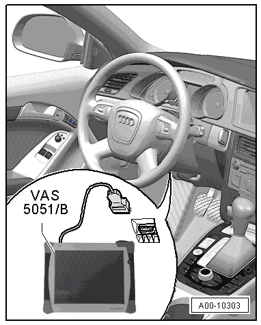
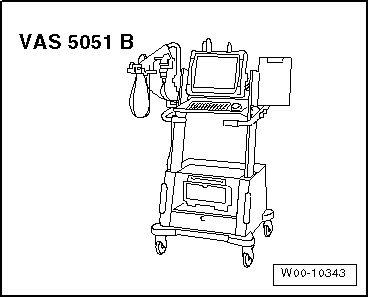
“Guided Fault Finding” using vehicle diagnostic, testing and information system -VAS 5051B- has been completed and all faults have been eliminated.
–  Using the vehicle diagnostic, testing and information system -VAS 5051B- in Guided Fault Finding mode, go to Function/Component Selection and select the following menu items:
t  Drive system
t  0B6 gearbox
t  01 - Self-diagnosis-compatible systems
t  02 - Gearbox electronics
t  02 - Gearbox electronics, Functions
t  02 - Read measured value block
–  Select measured value for “gear” from list on vehicle diagnostic, testing and information system -VAS 5051B-.
–  Compare the following readings:
t  Measured value for “gear” indicated on vehicle diagnostic, testing and information system -VAS 5051B-
t  Selector lever position
t  Gear indicated on selector lever position display -Y26- (on selector mechanism)
t  Selector lever position display -Y6- in instrument cluster
Requirement:
l  The displays should match
If the displays do not match:
–  Adjust selector lever cable → Chapter.
If the displays cannot be matched by adjusting the selector lever cable:
  A00-10303
Adjust selector lever cable to basic setting:
l  Tightening torque → Chapter
–  Carefully lever retainer frame for selector lever boot -1- out of centre console -arrows- using removal wedge -3409- and turn selector lever boot inside out over selector lever handle.
–  Shift selector lever to position “D”.
  A37-10040
–  Insert socket and key -T40031- through access hole -arrow- in selector mechanism and slacken bolt on selector lever cable approx. one turn.
  Note
t  Only loosen clamping bolt – do not remove.
t  Clamping bolt can only be accessed with selector lever in position “D”.
t  With clamping bolt loosened, selector lever must remain in position “D”.
  A37-10753
–  Use removal lever -80 - 200- to pry ball socket -1- on selector lever cable off selector shaft lever.
  Note
t  Do not bend or kink the selector lever cable.
t  Before installing, lightly grease cable eye and ball socket on selector lever cable with polycarbamide grease -G 052 142 A2-.
t  -Item 2- can be disregarded.
  A37-10860
–  Press selector shaft lever -1- on gearbox towards the rear as far as it will go -arrow- until parking lock engages.
  Note
When the parking lock has engaged it should no longer be possible to rotate both front wheels in one direction at the same time.
–  Then push selector shaft lever forward 3 notches so that gearbox is in position “D”.
–  Check that selector lever is also in position “D” inside the vehicle.
–  With vehicle diagnostic, testing and information system -VAS 5051B- in Guided Fault Finding mode, select 02 - Gearbox electronics and then the Read measured value block function.
–  Select “Measured value gear” on vehicle diagnostic, testing and information system -VAS 5051B-.
–  Compare the following readings:
t  Measured value for “gear” indicated on vehicle diagnostic, testing and information system -VAS 5051B-
t  Selector lever position
t  Gear indicated on selector lever position display -Y26- (on selector mechanism)
t  Selector lever position display -Y6- in instrument cluster
Requirement:
l  The displays should match
  A37-10863
–  Carefully press ball socket -1- of selector lever cable onto selector shaft lever in this position.
  Note
t  Take care not to bend selector shaft lever when pressing on cable; support lever if necessary, as otherwise selector mechanism can no longer be adjusted accurately.
t  -Item 2- can be disregarded.
–  Adjust selector lever cable → Chapter.
–  Check selector mechanism → Chapter.
  A37-10860

Exploded view - tunnel cross member, gearbox mounting and gearbox support > < ATF in gearbox