audi Workshop Repair Guides

Audi Workshop Service and Repair Manuals

Exploded view - input shaft with cover for input shaft > < ATF purging procedure
Removing and installing reverse gear clutch and determining shim thicknesses
Special tools and workshop equipment required
   
t  Digital depth gauge -VAS 6087-
t  Digital caliper, 150 mm -VAS 6335-
  W00-10365
t  2x ruler -T40100-
  W00-10297
t  Clean, flat measurement surface, e.g. compressor tool -T10285-
  W00-10286
Removing reverse gear clutch
  Note
t  → Chapter „Repair instructions“.
t  → Chapter „Rules for cleanliness when working on the gearbox“.
l  Gearbox must be removed and secured in a vertical position on engine and gearbox support → Chapter.
–  Remove input shaft → Chapter.
–  Take reverse gear clutch with corrugated washers -1 ... 5- out of gearbox.
–  Measure top shim -4- and bottom shim -2- and note down values.
  Note
The purpose of noting down the values for the originally fitted top shim -4- and bottom shim -2- is to provide a check for the newly determined shims as described below. If there is a large difference between the values for the old shims and the new shims, the measurement must be repeated.
Adjusting reverse gear clutch by determining shims:
  Note
The purpose of the following measurements is to determine the thickness of the top shim -4- and bottom shim -2- for setting the reverse gear clutch.
l  To ensure accuracy, the surfaces of all tools and components must be absolutely clean when performing the following measurements.
  A37-11037
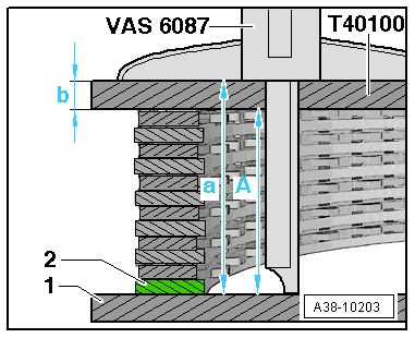
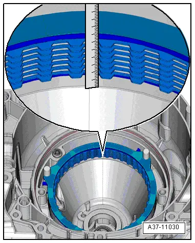
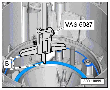
1. Calculating dimension -B-; measurement from contact surface of input shaft cover to contact surface of corrugated washer:
–  Clean contact surfaces and sealing surfaces on gearbox housing. Completely remove any remaining sealing material.
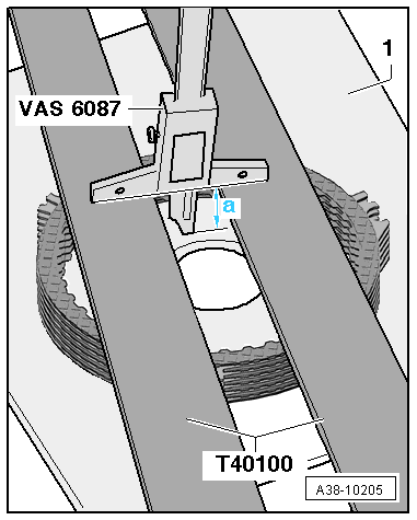
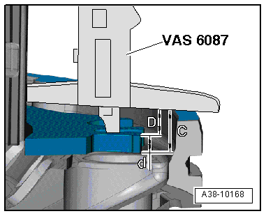
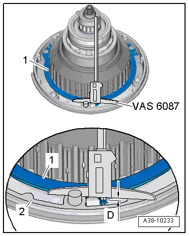
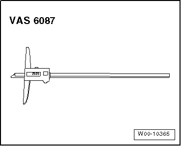
–  Use digital depth gauge -VAS 6087- to measure from contact surface of input shaft cover to contact surface of corrugated washer in gearbox housing.
–  Note down dimension „B1“.
–  Repeat measurement at two other points on the circumference and note down dimensions „B2“ and „B3“.
–  Calculate mean value -B- from the 3 measured values and note down.
Mean value:
B1 + B2 + B3
3
 = dimension -B-
–  Note down dimension -B-.
Example:
29,0 mm + 28,9 mm + 29,0 mm
3
 = 28.97 mm
In this example, dimension -B- = 28.97 mm.
  A38-10099
2. Calculating dimension -A-; measurement of compressed clutch pack:
l  The corrugated washer -2- is fitted beneath the clutch pack for the measurement.
l  Use a clean, flat measurement surface -1- as a base. Compressor tool -T10285- is used in the following description.
  A38-10203
–  First place corrugated washer -A- on measurement surface -1-.
–  Then alternately place friction plates -C- (7x) and outer plates -B- (6x) one at a time on corrugated washer (all aligned in the same position).
  A38-10211
–  Make sure that all plates are accurately aligned one on top of the other.
–  Place two rulers -T40100- on top of clutch pack.
  Note
The weight of the rulers -T40100- presses the air out from between the plates and exerts the specified 2.5 kg load on the corrugated washer so it is compressed.
–  Use digital depth gauge -VAS 6087- to measure down to working surface -1- and note down measured value „a1“.
l  When taking measurements, the digital depth gauge -VAS 6087- must make flush contact with both rulers -T40100-.
–  Repeat measurement on opposite side of clutch pack and note down measured value „a2“.
–  Move the two rulers -T40100- 90° from their first position.
–  Repeat measurements and note down measured values „a3“ and „a4“.
–  Calculate mean value -a- from the 4 measured values and note down.
   Mean value:
a1 + a2 + a3 + a4
4
 = -a-
  A38-10205
Calculating dimension -A-:
–  Measure and note down thickness -b- of rulers -T40100-.
   The height of the compressed clutch pack is -a- – -b- = dimension -A-.
–  Note down dimension -A-.
  A38-10203
Example: 
 Mean value measured with depth gauge
35,45 mm + 35,46 mm + 35,42 mm + 35,47 mm
4
 = -a-
35.45 mm
Thickness -b- of rulers -T40100-– 7.47 mm
=Dimension -A- of compressed clutch pack= 27.98 mm

   
3. Calculating dimension -C-; measurement from contact surface of input shaft cover to piston of reverse gear clutch:
  A38-10168
–  Place a clean outer plate -1- on input shaft (removed from gearbox).
  Note
The outer plate -1- is placed on the piston of the reverse gear clutch in order to obtain a correct measurement to the highest point of the piston. The thickness -d- of the outer plate -1- is subsequently added when calculating the height of the piston.
  A38-10167
–  Use digital depth gauge -VAS 6087- to measure from contact surface -2- of input shaft cover to previously fitted outer plate -1- and note down measured value „D1“.
–  Repeat measurement at another point on the circumference and note down measured value „D2“.
–  Calculate mean value -D- from the 2 measured values and note down.
   Mean value:
D1 + D2
2
 = -D-
  A38-10233
–  Remove previously fitted outer plate from input shaft and measure thickness -d- using digital caliper, 150 mm -VAS 6335-.
  A38-10212
Calculating dimension -C-:
Calculate dimension -C- from contact surface of input shaft cover to piston of reverse gear clutch:
-D- + -d- = dimension -C-
–  Note down dimension -C-.
  A38-10168
Example: 
 Mean value -D- = 
4,51 mm + 4,49 mm
2
 =
4.50 mm
+Thickness -d- of outer plate -1- fitted before measurement+ 1.95 mm
=Dimension -C- from contact surface of input shaft cover to piston of reverse gear clutch= 6.45 mm

4. Determining thickness of the two shims „Etot.“:
–  Calculate thickness of shims according to the following formula from noted dimensions „A“, „B“ and „C“ and a constant value of 3.0 mm for clearance:
   „B“ + „C“ – „A“ – 3.0 mm = „Etot.
–  Determine bottom shim „E1“ and top shim „E2“ from table → Anchor.
   
Thickness of both shims „Etot.
in mm
Thickness of bottom shim „E1
in mm
Thickness of top shim „E2
in mm
3.916 … 4.1651.902.15
4.166 … 4.4352.152.15
4.436 … 4.6751.902.65
4.676 … 4.9251.902.90
4.926 …5.1651.903.15
5.166 … 5.4252.153.15
5.426 … 5.6752.652.90
5.676 … 5.9252.653.15
5.926 … 6.1752.903.15
6.176 … 6.4003.153.15

  Note
Select correct shims from → Electronic parts catalogue.
Example:
The example is based on the following values:
t  Dimension „A“ = 27.98 mm
t  Dimension „B“ = 28.97 mm
t  Dimension „C“ = 6.45 mm.
t  Constant value for clearance = 3.0 mm
„B“ + „C“ – „A“ – 3.0 mm = „Etot.
28.97 mm + 6.45 mm – 27.98 mm – 3.0 mm = 4.44 mm
„Etot.“ = 4.44 mm
–  Thickness of bottom shim „E1“ from table: 1.90 mm
–  Thickness of top shim „E2“ from table: 2.65 mm
   
Installing reverse gear clutch
  Note
As an additional check, compare the thickness of the new shims as determined above with the thickness of the old shims as measured at the beginning of the procedure → Anchor. If there is a large difference between the values for the old shims and the new shims, the measurement must be repeated.
l  Thoroughly clean all components prior to installation.
–  Insert corrugated washer -6- in guides -1- (3x) in gearbox.
–  Insert bottom shim „E1-item 2- of calculated thickness in guides in gearbox.
–  Then alternately fit friction plates -3- and outer plates -5- in guides in gearbox (all aligned in the same position).
–  Finally insert top shim „E2-item 4- of calculated thickness in guides in gearbox.
  A37-11037
–  Align plates of reverse gear clutch using a straight-edge or similar.
l  The teeth must be set exactly in line.
–  Install input shaft → Chapter.
  A37-11030

Exploded view - input shaft with cover for input shaft > < ATF purging procedure