audi Workshop Repair Guides

Audi Workshop Service and Repair Manuals

Cylinder head > < Renewing oil seal for vibration damper
Removing and installing camshaft timing chain
Special tools and workshop equipment required
   
t  Counterhold tool -T10355-
  W00-10474
t  Assembly tool -T10352/2-
  W00-10736
t  Locking pin -T40011-
t  Locking tool -T40267-
t  Assembly tool -T40266-
Removing
–  Remove front end → Rep. gr.50.
–  Remove timing chain cover (top) → Chapter.
  W00-1089
  Caution
The timing valves have a left-hand thread.
–  Turn assembly tool -T10352/2- in direction of -arrow- to remove timing valve (left and right sides).
  A15-11239
–  Remove bolts -arrows- and detach bearing saddle.
  A15-11240
–  Turn vibration damper to „TDC“ position -arrow- using counterhold tool -T10355-.
l  Notch on vibration damper must align with arrow marking on cover for timing chains (bottom).
l  The markings -1- on the camshafts must face upwards.
–  Remove timing chain cover (bottom) → Chapter.
  A15-11244
–  Press retainer for oil pump chain tensioner in direction of -arrow- and lock in place using locking pin -T40011-.
–  Remove oil pump chain tensioner -1-.
  A15-11243
–  Compress circlip -arrow- for chain tensioner.
–  Press tensioning rail for timing chain in direction of -arrow- and lock in place using locking tool -T40267-.
–  Remove camshaft timing chain from camshaft sprockets and place onto camshaft journals.
  Note
The camshafts will move suddenly in direction of engine rotation.
  A15-11245
–  Remove tensioning rail for timing chain -2-.
–  Remove guide rail for camshaft timing chain -1-.
  A15-11246
–  Remove chain tensioner for balance shaft timing chain -1-.
–  Remove tensioning rail -2-.
–  Remove guide rail -4-.
  A15-10462
–  Remove bolt -arrow- for vibration damper.
–  Remove sprockets; to do so, remove oil pump chain.
–  Detach camshaft timing chain.
Installing
l  Tightening torques → Chapter „Camshaft timing chain - exploded view“
  A15-11339
–  Check TDC position of crankshaft; the marks -arrows- should be aligned.
–  Use a waterproof pen to mark cylinder block -1-.
  A15-11271
–  Mark tooth of drive chain sprocket -1- adjacent to marking -2- using waterproof pen.
  A15-11270
–  Turn idler gear/balance shaft to markings -arrow-.
  Note
  A15-10464
The links of the drive chain for balance shafts with coloured markings must be positioned at the markings on the chain sprockets.
–  Fit drive chain for balance shafts; links with coloured markings -arrows- must be positioned at markings on chain sprockets.
  A15-11272
–  Fit camshaft timing chain so that markings -arrows- are positioned on camshaft journals.
  A15-11273
–  Fit oil pump chain onto sprocket.
–  Pivot sprocket towards engine in direction of -arrow- and lock onto crankshaft. The marks -arrows- must align.
  A15-11274
–  Fit thrust piece -T10368- with bolt -arrow- for vibration damper.
  A15-11339
–  Fit guide rail for drive chain for balance shafts and tighten bolts -arrows-.
  A15-11276
–  Position link of drive chain for balance shafts with coloured marking -arrow- at marking on chain sprocket; fit tensioning rail for timing chain and tighten bolt -1-.
  A15-11275
–  Apply locking fluid and fit chain tensioner for timing chain -1-; for locking fluid refer to → Electronic parts catalogue.
  A15-10462
–  Check position again; timing chain links with coloured markings must be positioned at markings on chain sprockets.
  A15-10463
  Note
t  The following procedure must be performed in continuous sequence. This requires the assistance of a 2nd person.
t  
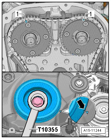
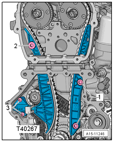
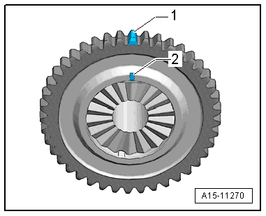
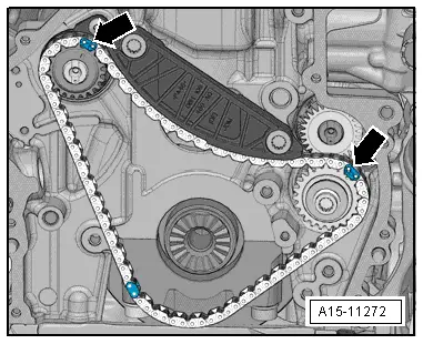
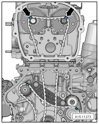
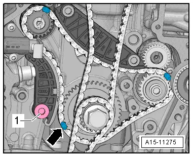
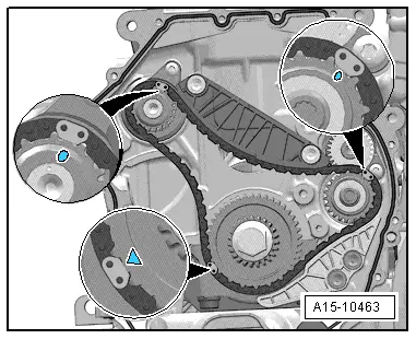
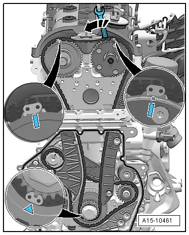
The camshaft timing chain links with coloured markings must be positioned at the markings on the chain sprockets.
–  Position camshaft timing chain links with coloured markings at markings on camshaft chain sprockets; to do so, turn camshafts using assembly tool -T40266-.
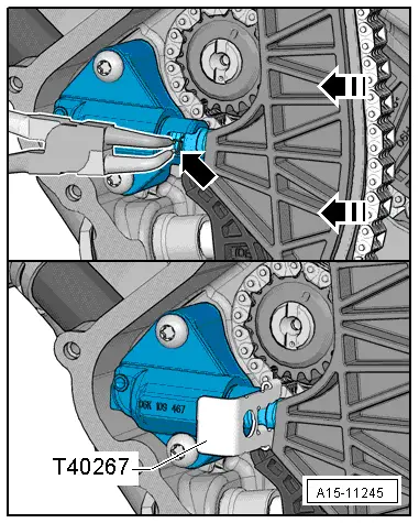
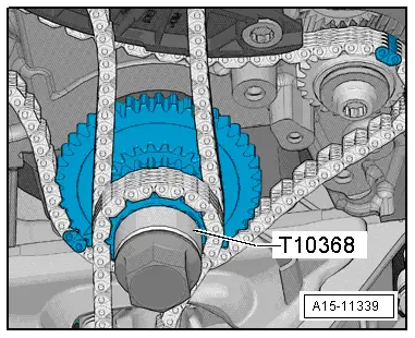
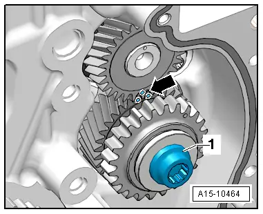
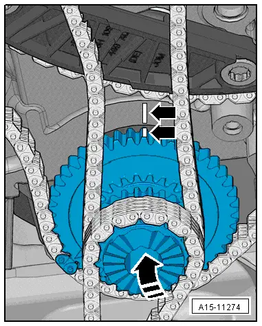
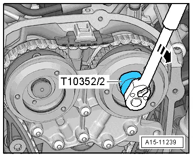
–  Fit camshaft timing chain link with coloured marking onto marking on chain sprocket of bottom sprocket assembly.
  A15-10461
–  Fit tensioning rail for timing chain and tighten bolt -2-.
–  Fit guide rail for camshaft timing chain and tighten bolts -1-.
  A15-11246
–  Attach bearing saddle and screw in bolts -arrows- hand-tight.
–  Remove locking tool -T40267-.
–  Tighten bolts -arrows- for bearing saddle → Chapter.
–  Install timing valves → Item.
Further assembly is basically carried out in reverse order of dismantling. Note the following:
–  Install timing chain cover (bottom) → Chapter.
–  Install timing chain cover (top) → Chapter.
–  Install poly V-belt tensioner → Chapter.
–  Install poly V-belt → Chapter.
–  Install front end → Rep. gr.50.
–  Install front bumper and bumper cover → Rep. gr.63.
  A15-11240

Cylinder head > < Renewing oil seal for vibration damper