
A5
| Charge air cooler - exploded view |

| 1 - | Charge air cooler |
| q | Removing and installing → Chapter |
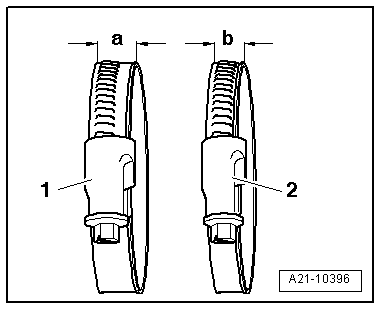
| 2 - | Hose clip |
| 3 - | Air hose |
| q | To turbocharger |
| q | Installing → Fig. |
| 4 - | Hose clip |
| 5 - | Hose clip |
| 6 - | Air hose |
| q | To intake manifold |
| q | Installing → Fig. |
| 7 - | Hose clip |
| 8 - | O-ring |
| q | Renew |
| 9 - | Charge pressure sender -G31-/intake air temperature sender -G42- |
| q | Removing and installing → Chapter |
| 10 - | Bolt |
| q | 5 Nm |
| 11 - | Rubber grommet |
| 12 - | Bush |
| 13 - | Nut |
| q | 9 Nm |
| 14 - | Rubber grommet |
| 15 - | Hose clip |
| 16 - | Air pipe |
| 17 - | Hose clip |
| 18 - | Air hose |
| q | From charge air cooler |
| q | Installing → Fig. |
| 19 - | Hose clip |
| 20 - | Bolt |
| q | 7 Nm |
| 21 - | Resonator |
| 22 - | Rubber grommet |
| 23 - | Hose clip |
| 24 - | Air hose |
| q | To resonator |
| q | Installing → Fig. |
 Note
Note
|
|