audi Workshop Repair Guides

Audi Workshop Service and Repair Manuals

Cylinder head > < Crankshaft
Removing and installing timing chain covers (left and right)
Special tools and workshop equipment required
t  Electric drill with plastic brush attachment
t  Safety goggles
t  Sealant → Electronic parts catalogue
   
Removing
  Note
Fit all cable ties in the original positions when installing.
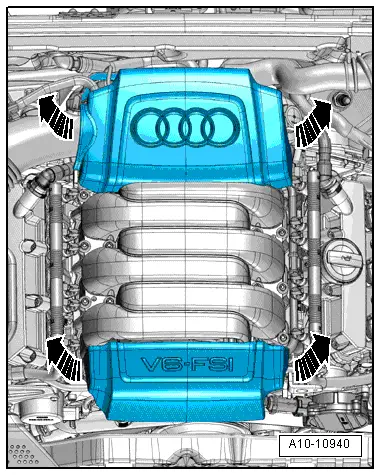
–  Pull off rear engine cover panel -top arrows-.
–  Vehicles without secondary air system: remove plenum chamber partition panel → Rep. Gr.50.
–  Vehicles with secondary air system: remove corresponding combination valve for secondary air system:
t  Country-specific version 1: left-side → Chapter; right-side → Chapter.
t  Country-specific version 2: left-side → Chapter; right-side → Chapter.
  A10-10940
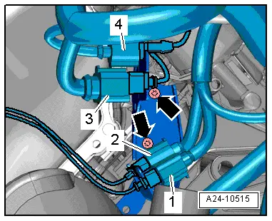
Timing chain cover (left-side):
–  Detach electrical connectors -1 … 4- from bracket and move clear to side.
  Note
Disregard -arrows-.
–  Move electrical wiring clear.
  A24-10515
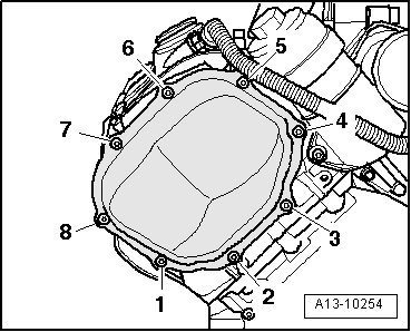
–  Unscrew bolts -1 ... 8- and remove timing chain cover (left-side).
  A13-10254
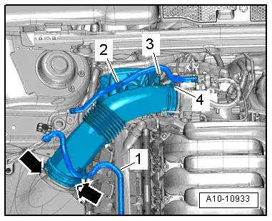
Timing chain cover (right-side):
–  Move fuel line -1- and line -2- (leading to activated charcoal filter) clear at air pipe.
–  Disconnect vacuum hose -3- from connection on air pipe.
–  Remove air pipe. To do so, release hose clip -4- and clamps -arrows-.
  A10-10933
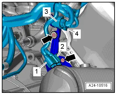
–  Detach electrical connectors -1 … 4- from bracket and move clear to side.
  Note
Disregard -arrows-.
  A24-10516
–  Unscrew bolts -1 ... 8- and remove timing chain cover (right-side).
  A13-10255
Installing
l  Tightening torques → Fig., → Fig..
  Caution
Protect lubrication system against contamination.
Cover exposed parts of the engine.
  WARNING
Protect eyes against injuries.
Wear safety goggles.
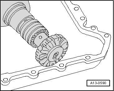
–  Remove remaining sealant on timing chain covers, cylinder block and cylinder head using rotating plastic brush or similar.
–  Clean sealing surfaces; they must be free of oil and grease.
  Note
  A13-0590
Note the use-by date of the sealant.
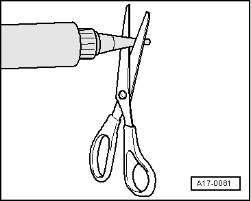
–  Cut off nozzle of tube at front marking (nozzle Ø approx. 2 mm).
  A17-0081
  Caution
Make sure lubrication system is not clogged by excess sealant.
The bead of sealant must not be thicker than specified.
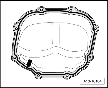
–  Apply sealant bead -arrow- onto the clean sealing surface of the timing chain cover (left-side) as illustrated.
l  Width of sealant bead: 2.5 mm.
  Note
The timing chain covers must be installed within 5 minutes after applying sealant.
  A13-10104
–  Install timing chain cover (left-side) and tighten bolts → Fig..
  A13-10254
–  Apply sealant bead -arrow- onto the clean sealing surface of the timing chain cover (right-side) as illustrated.
l  Width of sealant bead: 2.5 mm.
  A13-10104
–  Install timing chain cover (right-side) and tighten bolts → Fig..
Remaining installation steps are carried out in reverse sequence; note the following:
  Note
Secure all hose connections with the correct type of hose clips (same as original equipment) → Electronic parts catalogue.
–  Vehicles without secondary air system: install plenum chamber partition panel → Rep. Gr.50.
–  Vehicles with secondary air system: install corresponding combination valve for secondary air system:
t  Country-specific version 1: left-side → Chapter; right-side → Chapter.
t  Country-specific version 2: left-side → Chapter; right-side → Chapter.
  A13-10255

Cylinder head > < Crankshaft