
A5
| Pistons and conrods - exploded view |

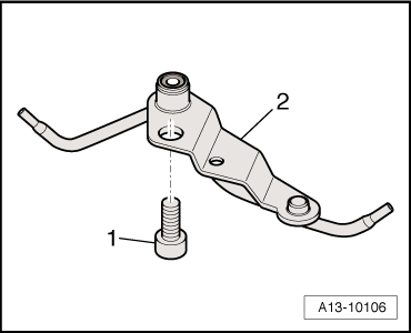
| 1 - | Bolts |
| q | Renew |
| q | Lubricate threads and contact surface |
| q | 30 Nm + turn 90° further |
| 2 - | Conrod bearing cap |
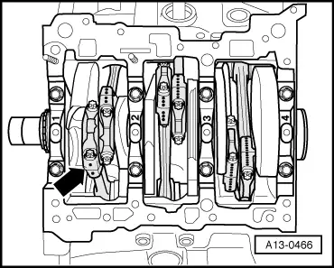
| q | Mark installation position for re-installation |
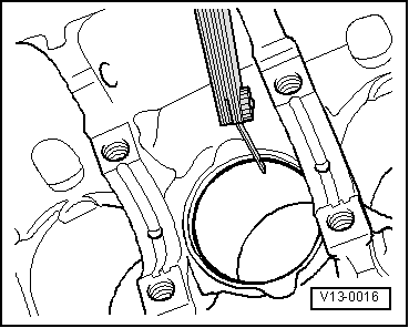
| q | Mark cylinder allocation in colour -B- → Fig. |
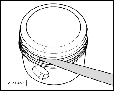
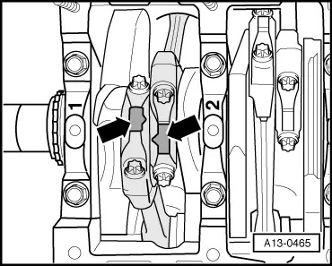
| q | Note when fitting bearing cap: the wide contact shoulder -A- must point towards same side on conrod and conrod bearing cap |
| q | Installation position of conrod pairs → Fig. |
| 3 - | Bearing shell |
| q | Ensure that retaining lugs are securely seated. |
| q | Mark used bearing shells for re-installation but not on bearing surface |
| q | Bearing shells worn down to base layer must be renewed |
| 4 - | Conrod |
| q | Only renew as a complete set |
| q | Mark cylinder allocation in colour -B- → Fig. |
| q | Note when fitting bearing cap: the wide contact shoulder -A- must point towards same side on conrod and conrod bearing cap |
| q | Installation position of conrod pairs → Fig. |
| q | Measuring radial clearance → Chapter |
| 5 - | Piston pin |
| q | If difficult to remove, heat piston to approx. 60 °C |
| q | Remove and install using drift -VW 222 A- |
| 6 - | Circlip |
| q | Renew |
| 7 - | Piston |
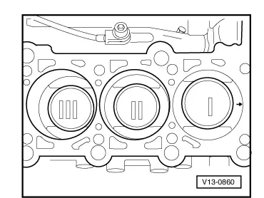
| q | Mark installation position and cylinder number → Fig. |
| q | Arrow on piston crown points to pulley end |
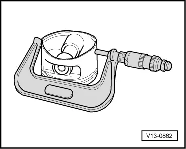
| q | Checking → Fig. |
| q | Renew piston if cracking is visible on piston crown or piston skirt |
| q | Install using piston ring clamp |
| q | Piston and cylinder dimensions → Chapter |
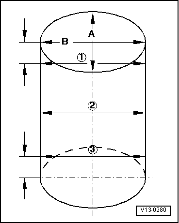
| q | Measuring cylinder bore → Fig. |
| 8 - | Piston rings |
| q | Offset gaps by 120° |
| q | Use piston ring pliers to remove and install |
| q | Installation position: marking “TOP” or side with lettering faces towards piston crown |
| q | Measuring ring gap → Fig. |
| q | Measuring ring-to-groove clearance → Fig. |
| Piston ring | new mm | Wear limit mm |
| 1st compression ring | 0.35 … 0.50 | 0.8 |
| 2nd compression ring | 0.60 … 0.80 | 1.0 |
| Oil scraper ring | 0.25 … 0.50 | 0.8 |
|
|
| Piston ring | new mm | Wear limit mm |
| Compression rings | 0.02 … 0.08 | 0.20 |
| Oil scraper ring | 0.02 … 0.08 | 0.15 |
|
|
|
|
|
|
 Caution
 Note
Note
|
|
|
|
Note
|
|