audi Workshop Repair Guides

Audi Workshop Service and Repair Manuals

Removing and installing engine - vehicles with multitronic gearbox 0AW > < Safety precautions
Removing engine
   
Removing engine
Special tools and workshop equipment required
t  Removal lever -80 - 200-
t  Used oil collection and extraction unit -V.A.G 1782-
t  Stepladder -VAS 5085-
t  Engine bung set -VAS 6122-
t  Scissor-type assembly platform -VAS 6131 A- with support set for Audi -VAS 6131/10- and supplementary set -VAS 6131/13-
t  Drip tray for workshop hoist -VAS 6208-

   
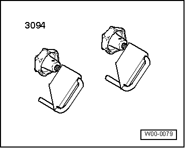
t  Hose clamps for hoses up to 25 mm -3094-
  W00-0079
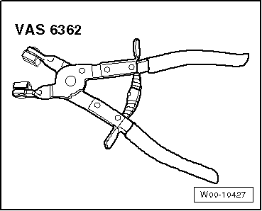
t  Hose clip pliers -VAS 6362-
  W00-10427
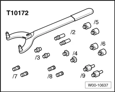
t  Counterhold tool -T10172- with -T10172/5- for vehicles with four-wheel drive
  W00-10637
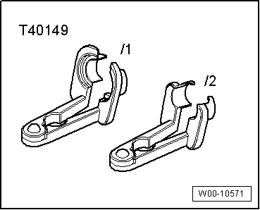
t  Release tool -T40149-
  W00-10571
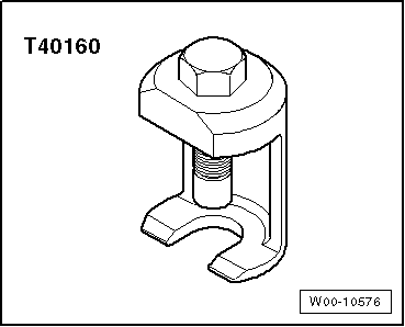
t  Puller -T40160-
Procedure
  WARNING
Make sure the vehicle cannot tip over when the engine is removed.
Secure the vehicle, to do so, the luggage compartment must be empty.
–  Set front wheels to straight-ahead position.
  Note
On four-wheel drive vehicles the electromechanical parking brake must be released before disconnecting the battery, so that the propshaft can be turned during removal.
  W00-10576
  Caution
Electronic components are susceptible to damage.
Observe notes on procedure for disconnecting the battery.
–  Switch off ignition and take out ignition key.
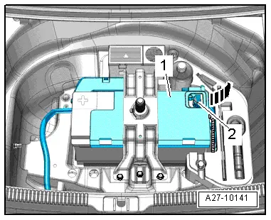
–  Disconnect earth wire -2- from battery terminal → Electrical system; Rep. gr.27.
–  Discharge refrigerant system → Air conditioner with refrigerant R134a.
–  Extract hydraulic fluid for power steering from reservoir using used oil collection and extraction unit -V.A.G 1782-.
  A27-10141
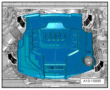
–  Remove engine cover panel -arrows-.
  WARNING
Hot steam/hot coolant can escape - risk of scalding.
t  The cooling system is under pressure when the engine is hot.
t  To allow pressure to dissipate, cover filler cap on coolant expansion tank with cloth and open carefully.
–  Open filler cap on coolant expansion tank.
  A10-10890
–  Remove both front wheels.
–  Remove front left and front right wheel housing liners → Rep. gr.66.
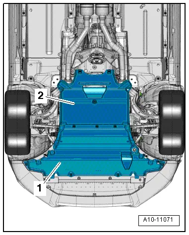
–  Remove noise insulation panels -1- and -2- → Rep. gr.66.
  A10-11071
–  Place drip tray for workshop hoist -VAS 6208- beneath engine.
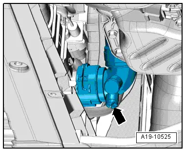
–  Remove drain plug -arrow- at connection and drain off coolant.
–  Then detach connection from radiator (lift retaining clip).
  A19-10525
–  Release hose clip -arrow-, disconnect coolant hose from coolant pipe (left-side) and drain off coolant.
  A19-10526
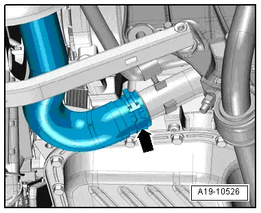
–  Vehicles with plug-in connector at coolant pipe (bottom right): Lift retaining clip -arrow-, disconnect coolant hose and drain off coolant.
  A19-10527
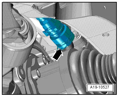
–  Vehicles with plug-in connector at longitudinal member: Lift retaining clip -arrow-, disconnect coolant hose and drain off coolant.
  A19-10908
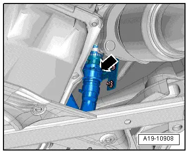
–  Position used oil collection and extraction unit -V.A.G 1782- below connection point.
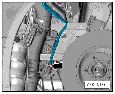
–  Disconnect hydraulic fluid return line -arrow- for power steering.
–  Seal off open pipes/lines and connections with clean plugs from engine bung set -VAS 6122-.
  A48-10178
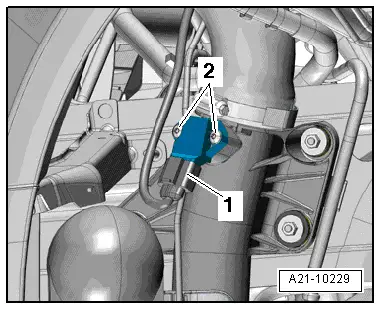
–  Unplug electrical connector -1- at charge pressure sender -G31- and move electrical wiring clear.
  Note
Disregard -item 2-.
  A21-10229
–  Unscrew nut -arrow- on longitudinal member (right-side) and move earth cables clear.
  A10-10843
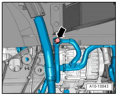
–  Unplug electrical connector -1- and, if fitted, -2- for radiator fan (push retainer to the rear -arrow- and press down release catch).
–  Move electrical wiring clear.
  A19-10529
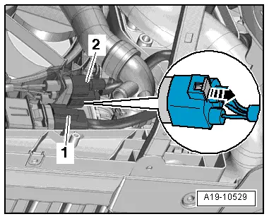
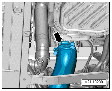
–  Release hose clip -arrow-, disconnect air hose from air pipe and move to one side.
  A21-10230
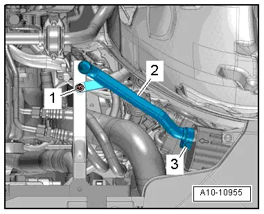
–  On vehicles with auxiliary heater: remove nut -1-, loosen clamp -3- and detach exhaust pipe -2- for auxiliary heater
  A10-10955
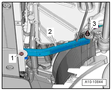
–  Remove bolt -1- and nut -3- on both sides and detach strut -2- for lock carrier.
  A10-10844
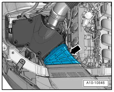
–  Remove air duct -arrow-.
  A10-10846
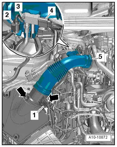
–  Unplug electrical connector -1- from air mass meter -G70-.
–  Unscrew bolt -3- and move clear exhaust gas pressure sensor 1 -G450--item 4- at air pipe.
–  Unplug electrical connector -2- and move air pipe clear.
–  Remove air hose and air mass meter -G70-. To do so, release hose clip -5- and clamps -arrows-.
  A10-10872
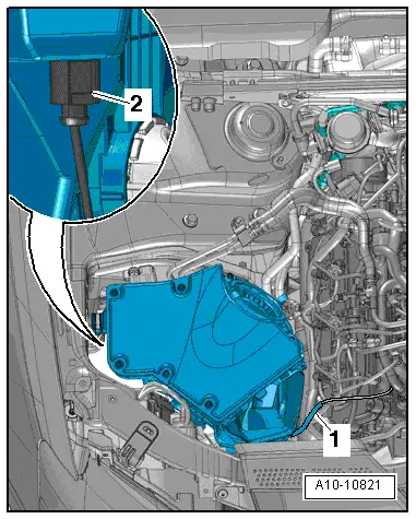
–  Disconnect vacuum line -1-.
–  Detach air cleaner housing, unplug electrical connector -2- at air filter bypass flap valve -N275- on reverse side of air cleaner and move electrical wiring clear.
  A10-10821
  Caution
Take care to keep components clean.
Observe rules for cleanliness when working on the fuel supply system → Chapter.
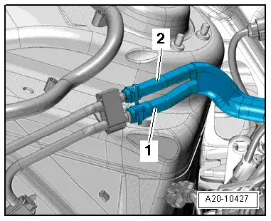
–  Disconnect fuel supply hose -1- and fuel return hose -2-.
  A20-10427
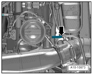
–  If fitted, disconnect vacuum line -arrow-.
  A10-10873
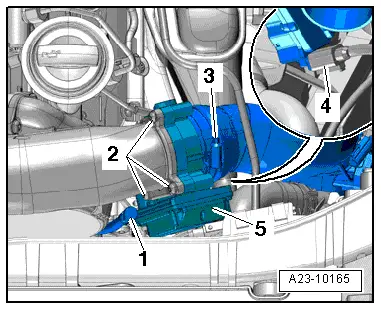
–  If fitted, pull out oil dipstick -1-.
–  Release hose clip -3- and detach air hose.
–  Unplug electrical connector -4-.
–  Remove bolts -2- and detach throttle valve module -J338--item 5-.
  Note
  A23-10165
Lay a cloth under the separating point to catch escaping hydraulic fluid.
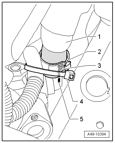
–  Cut open cable tie -4-.
–  Clamp off hydraulic hose -1- using hose clamp -3094-, release hose clip -2- and disconnect hose from power steering pump.
–  Seal off open pipes/lines and connections with clean plugs from engine bung set -VAS 6122-.
  Note
Disregard -items 3, 5-.
  A48-10394
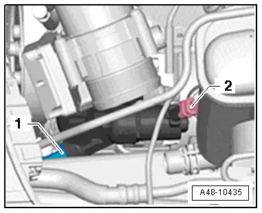
–  If fitted, unplug electrical connector -2-.
  Note
Disregard -item 1-.
  A48-10435
  Caution
Danger of damage to refrigerant lines and hoses.
Do NOT stretch, kink or bend refrigerant lines and hoses.
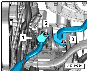
–  Remove bolt -2-, disconnect refrigerant line from air conditioner compressor and move to one side.
–  Seal off open pipes/lines and connections with clean plugs from engine bung set -VAS 6122-.
  Note
Disregard -items 1, 3-.
  A87-10396
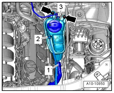
–  Disconnect coolant hose -3- from coolant expansion tank.
  Note
Disregard items marked -1, 2- and -arrows-.
  A10-10850
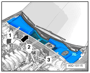
–  Remove seal -arrow-.
–  Remove plenum chamber cover → Rep. gr.50.
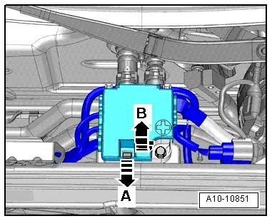
  A92-10115
–  Release retainer -arrow A- and open cover -arrow B-.
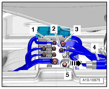
  A10-10851
–  Remove nuts -1 ... 3- for electrical wiring.
–  Detach electrical connector -4- from bracket and unplug.
–  Remove bolt -5- and detach terminal 30 wiring junction 2 -TV22- from body brace -arrow-.
  A10-10875
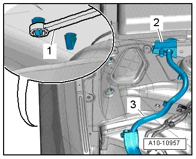
–  Working from wheel housing, release catches using a 5.5 mm ring spanner -item 1- and remove wiring protector -2- from above.
–  Release wiring harness -3- leading to alternator and starter using removal lever -80 - 200- and move clear.
  A10-10957
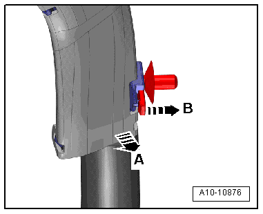
–  Wiring duct (version 1): release catch -arrow B- and move wiring duct clear by pulling it towards front -arrow A-.
  A10-10876
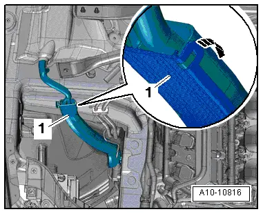
–  Wiring duct (version 2): release catch -arrow- to open wiring duct -1- and move wiring harness clear.
  A10-10816
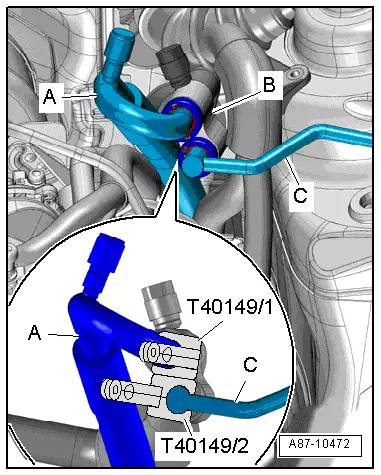
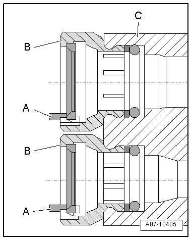
–  Press refrigerant lines -A- and -C- by hand as far as stop into connection piece -B- for refrigerant line with internal heat exchanger.
–  Spray area around refrigerant lines with silicone-free lubricant.
–  Fit release tool for air conditioner line -T40149/1- onto refrigerant line -A- and release tool for air conditioner line -T40149/2- onto refrigerant line -C- so that both tools engage audibly. This releases the retaining lugs.
–  Using release tools for air conditioner line, pull refrigerant lines -A- and -C- out of connection piece -B- for refrigerant line with internal heat exchanger.
  Note
  A87-10472
t  If it is not possible to pull out the refrigerant lines, do NOT attempt to turn the refrigerant lines in connection piece -C-.
t  In this case you will have to cut open the connectors -B- and take out the retaining rings -A-.
t  When cutting open the connectors, take care not to damage the connection piece -C- for the refrigerant line with internal heat exchanger.
  A87-10405
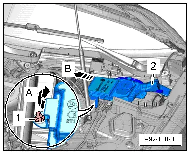
–  Remove nut -1- and swivel filler neck for washer fluid reservoir slightly upwards -arrow A-.
–  Pull filler neck -2- with filler pipe out of washer fluid reservoir and through opening in body -arrow B-.
  A92-10091
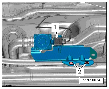
–  On vehicles with auxiliary heater: remove bolts -2- and move pump unit -1- clear to one side.
  A19-10624
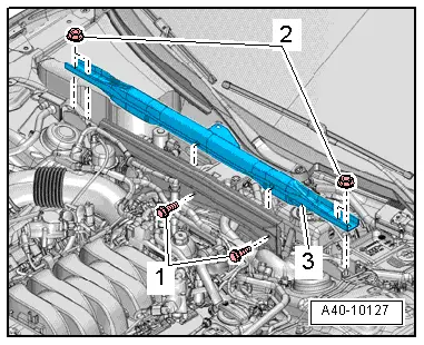
–  Remove bolts -1- and nuts -2- and detach body brace -3-.
  A40-10127
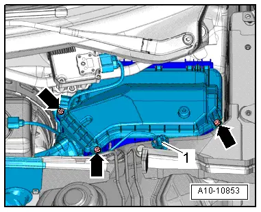
–  Remove bolts -arrows- and detach cover for electronics box in engine compartment.
–  Remove nut -1- and move electrical wiring clear.
  A10-10853
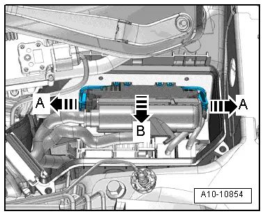
–  Release catches -arrows A- and take out engine control unit -arrow B-.
  A10-10854
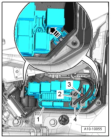
–  If fitted, unplug electrical connector -2-.
–  Unplug electrical connectors -4- and unscrew nut -3- for wiring.
–  Release catches -arrow- and detach relay carrier with fuse holder -1-.
–  Disengage engine wiring harness at electronics box in engine compartment and move clear.
  A10-10855
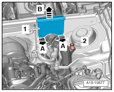
–  Release catches -arrows A- and lift off wiring protector -1--arrow B-.
–  Unscrew earth stud -2- and move wiring harness clear.
–  Place wiring harness on engine and secure engine control unit to prevent it from dropping.
  A10-10877
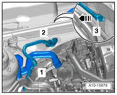
–  Release hose clip -1- and detach coolant hose.
–  Disconnect vacuum hose -3- on rear side of plenum chamber partition panel in direction of -arrow- and detach vacuum connection -2- from plenum chamber partition panel.
  A10-10878
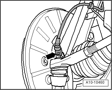
–  Unplug electrical connectors -arrow- at front wheel speed sensors on both sides.
  A10-10460
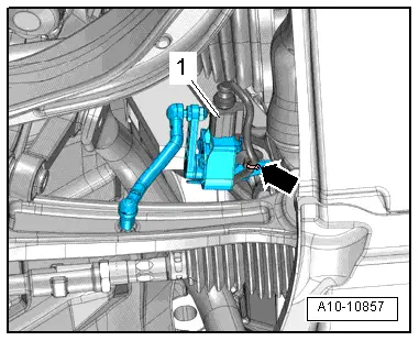
–  If fitted, unplug electrical connector -1- from front left vehicle level sender -G78- and front right vehicle level sender -G289- and move wiring clear -arrow-.
  A10-10857
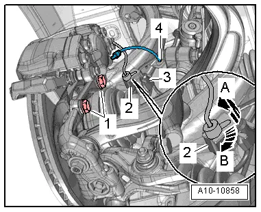
–  Release electrical connector -2- at bracket by pulling retainer catch to the rear -arrow A- and turning connector approx. 90° clockwise -arrow B-.
–  Move clear electrical wire -3- and brake hose -4- at bracket.
–  Remove bolts -1- and tie up brake caliper with attached brake hose in wheel housing.
  Caution
Avoid damage to brake pistons.
Do not operate brake pedal with brake caliper removed.
  A10-10858
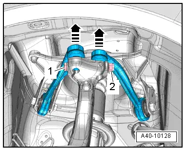
–  Remove nut -2- and pull out bolt -1-.
–  Pull upper suspension links upwards out of wheel bearing housing -arrows-.
–  Perform the same work steps on the other side of the vehicle.
  A40-10128
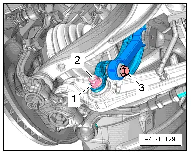
A5 up to vehicle identification no. 8T-8-011200:
–  Remove bolt -3- for anti-roll bar on both sides.
–  Remove nut -1- on both sides.
  Note
The bolts -2- are removed at a later stage.
  A40-10129
A4 (all), A5 from vehicle identification no. 8T-8-011201 onwards:
–  Remove bolt -1- for anti-roll bar on both sides.
–  Remove nut -3- on both sides.
  Note
The bolts -2- are removed at a later stage.
All vehicles (continued):
  Caution
Risk of damage to running gear components.
The vehicle must NOT be lowered onto its wheels if the engine/gearbox mountings, steering box or subframe cross brace are not properly installed.
  A40-10132
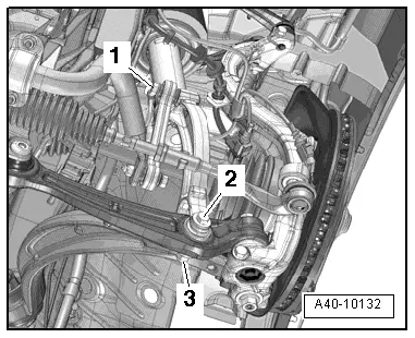
A4 (all), A5 Coupé:
–  Remove nut -1- for power steering hydraulic line.
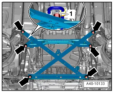
–  Remove bolts -arrows- and detach subframe cross brace.
  Note
Illustration shows the installation position on a vehicle with dynamic steering.
  A40-10133
A5 Cabriolet:
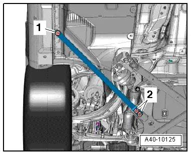
–  Remove bolts -1- and -2- on both sides and detach strut.
  A40-10125
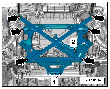
–  Remove bolt -2- for power steering hydraulic line.
–  Remove bolts -1- and -arrows- and detach subframe cross brace.
  A40-10134
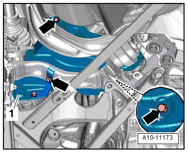
All vehicles (continued):
–  If fitted, remove bolts -arrows- on both sides and detach heat shield -1-.
  A10-11173
  Caution
Risk of damage to coil connector for airbag.
t  Make sure that front wheels are in straight-ahead position before removing universal joint from steering box.
t  Do not alter the position of the steering wheel or the steering gear from this point onwards.
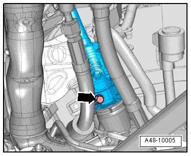
–  Remove bolt -arrow- for universal joint → Rep. gr.48.
–  Separate universal joint from steering box and move clear to the top as far as possible.
  A48-10005
–  Remove bolt -2- and tie up clutch slave cylinder at side of engine compartment.
  Caution
Avoid damage to clutch slave cylinder.
Do not press clutch pedal after removing slave cylinder.
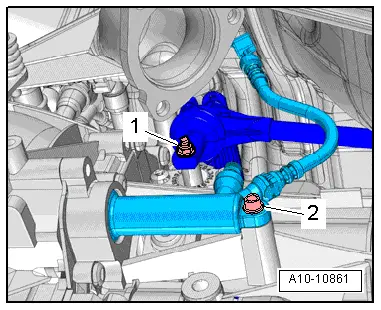
–  Remove nut -1- for selector rod.
  A10-10861
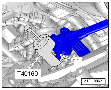
–  Apply puller -T40160- and pull off selector rod -1-.
  A10-10862
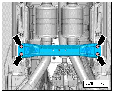
–  Remove bolts -arrows- and detach front cross member.
  A26-10532
  Caution
Risk of damage to flexible joint in front exhaust pipe.
Do NOT bend flexible joint in front exhaust pipe more than 10°.
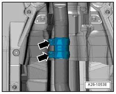
–  Loosen bolted connections -arrows- and push clamp towards rear.
  A26-10538
Vehicles with four-wheel drive:
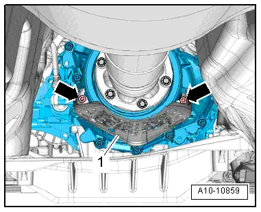
–  If fitted, remove bolts -arrows- and detach heat shield -1- for propshaft.
  A10-10859
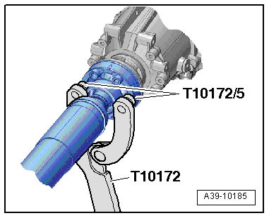
–  Remove bolts connecting propshaft to gearbox (use counterhold tool -T10172- with -T10172/5-).
–  Slide propshaft towards rear final drive; the constant velocity joints can be moved axially.
–  Tie up propshaft on one side.
  A39-10185
Set up the scissor-type assembly platform as follows:
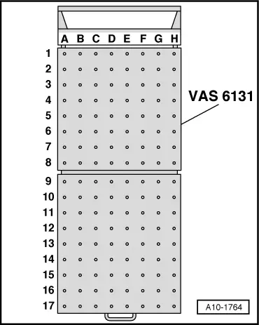
–  Set up scissor-type assembly platform -VAS 6131 A- with support set for Audi -VAS 6131/10- and supplementary set -VAS 6131/13- as follows:
  A10-1764
Platform coordinatesParts of support set for Audi -VAS 6131/10- and supplementary set -VAS 6131/13-
B4/13-4/10-4/10-5/13-1
G4/13-4/10-4/10-5/13-1
B6/10-1/10-2/10-5/10-11
G6/10-1/10-2/10-5/10-11
A8+C8/13-6/13-2
F8+H8/13-6/13-2
C14/10-1/10-3/10-5/10-13
F14/10-1/10-3/10-5/10-10
F17/10-1/10-4/10-5/13-2

–  Bolt the support elements onto the scissor-type assembly platform hand-tight to start with.
–  Position scissor-type assembly platform -VAS 6131 A- horizontally.
l  Take note of spirit level (bubble gauge).
–  Position scissor-type assembly platform -VAS 6131 A- below engine/gearbox assembly.
   
  WARNING
Accident risk if subframe mountings are detached.
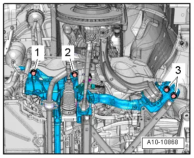
Subframe bolts -2- and -3- must not be loosened.
–  Remove subframe bolts -1- on both sides.
  A10-10868
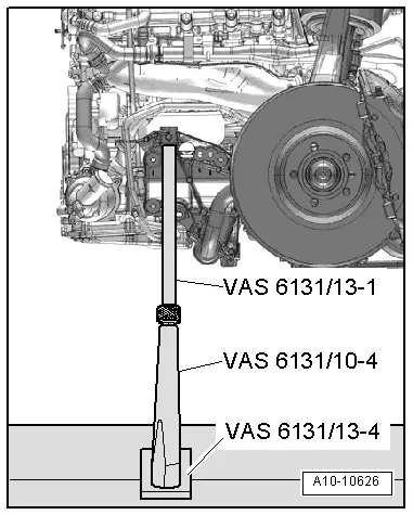
–  Position support elements from -VAS 6131/10- and -VAS 6131/13- at front left and right of subframe as shown.
–  Make sure that threaded spindles are screwed in completely.
  A10-10626
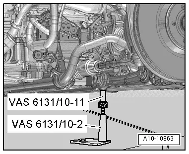
–  Position support elements from -VAS 6131/10- (rear left and right) at front attachment points of subframe cross brace as shown.
  A10-10863
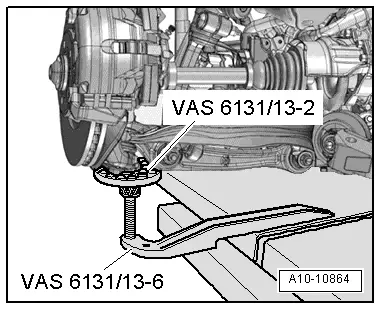
–  Position support elements from -VAS 6131/13- under left and right wheel bearing housings as shown.
  A10-10864
–  Detach retaining clips for noise insulation from tunnel cross member.
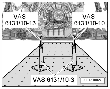
–  Position support elements from -VAS 6131/10- (rear left and right) at tunnel cross member as shown.
–  Turn all spindles for support elements upwards until all locating lugs make contact with mounting points.
  A10-10865
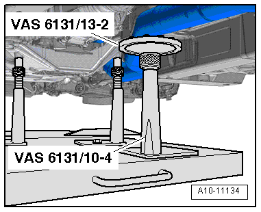
–  Position support elements from -VAS 6131/10- and -VAS 6131/13- underneath front exhaust pipe, as shown in illustration.
–  Tighten base plates for support elements to 20 Nm on scissor-type assembly platform -VAS 6131 A-.
  A10-11134
–  Mark installation position of subframe on longitudinal members with felt-tip pen.
–  Unscrew subframe bolts -2- and -3- on both sides in several stages and in diagonal sequence.
  Note
Disregard -item 1-.
  A10-10868
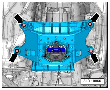
–  Remove bolts -arrows- for tunnel cross member.
  A10-10866
A5 up to vehicle identification no. 8T-8-011200:
–  Remove bolt -2- on both sides.
  A40-10129
A4 (all), A5 from vehicle identification no. 8T-8-011201 onwards:
–  Remove bolt -2- on both sides.
All vehicles (continued):
  Caution
Danger of damage to hoses, pipes and wiring connections and to engine compartment.
t  Check that all hoses and wiring connections between engine, gearbox, subframe and body have been detached.
t  Carefully guide out engine/gearbox assembly with subframe from engine compartment when lowering.
  A40-10132
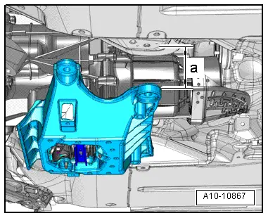
–  Lower engine/gearbox assembly using scissor-type assembly platform -VAS 6131 A- initially only as far as distance -a-.
l  Dimension -a- = 100 mm (maximum).
  A10-10867
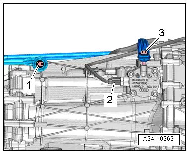
–  Remove bolts -1- and -3- for selector rod and push rod.
  Note
Disregard -item 2-.
–  Lower engine/gearbox assembly further.
–  Pull out scissor-type assembly platform -VAS 6131 A- with engine/gearbox assembly from underneath vehicle.
  A34-10369

Removing and installing engine - vehicles with multitronic gearbox 0AW > < Safety precautions