A5
| Removing cylinder head - engine code CAPA |

| Special tools and workshop equipment required |
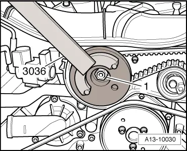
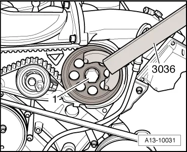
| t | Counterhold tool -3036- |
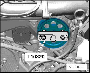
| t | Puller -T10320- |
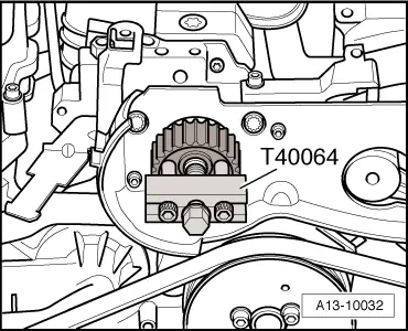
| t | Puller -T40064- |
|
|
|
|
|
|
|
|
|
|
|
|
|
|
|
|
 Note
Note
|
|
Note
|
|
|
|
Note
|
|
|
|
|
|
|
|
|
|
Note
Note |
|
|
|
 Caution
|
|