audi Workshop Repair Guides

Audi Workshop Service and Repair Manuals

Checking compression > < Cylinder head - exploded view
Removing and installing cylinder head
Special tools and workshop equipment required
   
t  Hose clip pliers -VAS 6362-
  W00-10427
Removing
–  Drain coolant → Chapter.
–  Remove turbocharger → Chapter.
–  Remove intake manifold → Rep. gr.23.
–  Remove corresponding camshafts:
t  → Chapter „Removing camshafts and re-installing used camshafts - cylinder bank 1 (right-side)“
t  → Chapter „Removing camshafts and re-installing used camshafts - cylinder bank 2 (left-side)“
  A23-10532
Cylinder head (left-side):
–  Release hose clip -1- and detach coolant hose.
  Note
Disregard -item 2-.
  A19-11136
–  Remove bolts -1- and detach exhaust gas recirculation pipe.
  Note
Disregard -item 2-.
  A26-10969
–  Unscrew union nut -left arrow- and detach high-pressure pipe -1-.
  Note
Disregard -arrow- on right-side of illustration.
  A23-10548
Cylinder head (right-side):
–  Remove front coolant pipe → Chapter.
–  Release hose clip -1-, lift retaining clip -2- and detach coolant hoses.
  Note
Disregard -arrows-.
  A19-11226
–  Unscrew union nut -right arrow- and detach high-pressure pipe -1-.
  Note
Ignore -arrow on left side of illustration-.
  A23-10549
–  Remove banjo bolt -arrow-.
  A15-10989
–  Remove guide pin -1- for guide rail and -2- for tensioning rail.
  Note
Ignore -T40246-.
  A15-11050
Continuation for both sides:
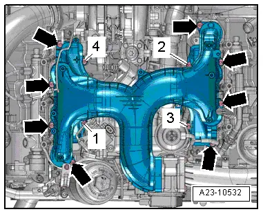
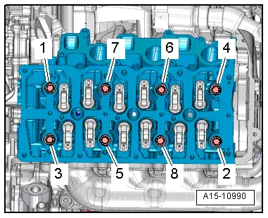
–  Slacken cylinder head bolts in the sequence -1 ... 8-.
–  Remove bolts and carefully take off cylinder head.
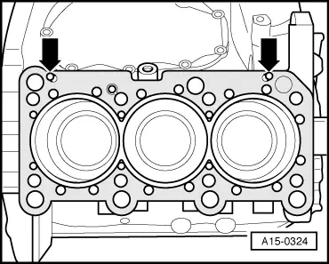
  Caution
Risk of damage to glow plugs when putting down cylinder head.
After removal, the cylinder head must not be put down on the gasket side with the glow plugs still installed, because the glow plugs project slightly beyond the gasket surface.
Installing
Installation is carried out in the reverse order; note the following:
Tightening torques
l  → Chapter „Cylinder head - exploded view“.
l  → Fig. „„Cylinder head - tightening torque and sequence““.
l  → Fig. „„Installing air hoses with screw-type clips““.
l  → Chapter „Exhaust gas recirculation system - exploded view“.
  Caution
Avoid damage to sealing surfaces.
t  Carefully remove sealant residue from cylinder head and cylinder block.
t  Ensure that no long scores or scratches are made on the surfaces.
Avoid damage to cylinder block.
No oil or coolant must be allowed to remain in the blind holes for the cylinder head bolts in the cylinder block.
Risk of leaks at cylinder head gasket.
t  Carefully remove any remaining emery and abrasive material.
t  
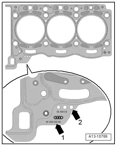
Do not remove new cylinder head gasket from packaging until it is ready to be fitted.
t  Handle the cylinder head gasket very carefully to prevent damage to the silicone coating or the indented area of the gasket.
Avoid damage to open valves.
When installing an exchange cylinder head, the plastic protectors fitted to protect the open valves should not be removed until the cylinder head is ready to be fitted.
Avoid damage to valves and piston crowns after working on valve gear.
Turn the engine carefully at least 2 rotations to ensure that none of the valves make contact when the starter is operated.
  Note
t  Renew the bolts tightened with specified tightening angle.
t  Renew self-locking nuts as well as seals, gaskets and O-rings.
t  Cylinder heads must not be reworked on TDI engines.
t  When installing an exchange cylinder head, the contact surfaces between roller rocker fingers and cams must be oiled before installing the cylinder head cover.
t  Secure all hose connections with the correct type of hose clips (same as original equipment) → Electronic parts catalogue.
t  After fitting a new cylinder head or cylinder head gasket, change the engine oil and the coolant in the entire cooling system.
  A15-10990
–  Before installing cylinder head, set crankshaft and camshafts to „TDC“:
l  Crankshaft -1- locked in „TDC“ position with locking pin -3242-.
  A15-11026
l  Camshafts locked with adjustment pin -T40060-.
l  The side pin -arrow- on the adjustment pin -T40060- must be in line with the imaginary line between the adjustment pin and the centre of the camshaft on cylinder bank 1 (right-side).
  A15-10999
l  The side pin -arrow- on the adjustment pin -T40060- must be in line with the imaginary line between the adjustment pin and the centre of the camshaft on cylinder bank 2 (left-side).
  A15-11000
–  Note cylinder head gasket identification:
1 - Part number
2 - Holes
  Note
t  If the cylinder head gasket or cylinder head have been replaced, select the new cylinder head gasket according to the number of holes on the old gasket.
t  If parts of the crankshaft drive have been renewed, the new cylinder head gasket must be selected by measuring the piston projection at „TDC“ → Chapter.
t  The gaskets for the left and right cylinder heads have different shapes and cannot be interchanged.
  A13-10786
–  Place cylinder head gasket in position.
l  Pay attention to dowel sleeves -arrows- in cylinder block.
l  Installation position of cylinder head gasket: the word „oben“ (top) or the part number should face towards the cylinder head.
–  Fit cylinder head.
–  Tighten cylinder head bolts → Fig..
  Note
Cylinder head bolts do not have to be torqued down again later after repair work.
–  Install coolant pipe (front) → Chapter.
–  Install high-pressure pipes → Rep. gr.23.
–  Install camshafts:
t  → Chapter „Removing camshafts and re-installing used camshafts - cylinder bank 1 (right-side)“
t  → Chapter „Removing camshafts and re-installing used camshafts - cylinder bank 2 (left-side)“
–  Install intake manifold → Rep. gr.23.
–  Install turbocharger → Chapter.
–  Change engine oil → Booklet811, → Booklet812 or → Booklet818.
–  Connect coolant hose with plug-in connector → Fig..
–  Fill cooling system with fresh coolant → Anchor.
  A15-0324

Checking compression > < Cylinder head - exploded view