audi Workshop Repair Guides

Audi Workshop Service and Repair Manuals

Chain drive > < Cylinder head
Removing and installing camshafts
   
t  Special wrench -T10035-
  W00-0946
t  Tool set for FSI engines -T10133-
  W00-1258
t  Locating pins -T40116-
t  Adapter -T40257-
t  Wrench -T40263-
t  Electric drill with plastic brush attachment
t  Safety goggles
t  Sealant → Electronic parts catalogue
Removing
  Note
The following description is for removing and installing on cylinder head (left-side).
–  Remove timing chain from camshafts on relevant side → Chapter.
  W00-10394
–  Unplug electrical connectors:
1 - at camshaft control valve 2 -N208-
2 - at fuel pressure sender -G247-
3 - at high-pressure pump (left-side)
4 - at Hall sender 2 -G163-
–  Remove bolt -5- and move wiring harness clear.
  A15-10482
–  Remove high-pressure pump → Rep. gr.24.
  A24-10344
–  Remove locking pin -3242-.
  A13-0611
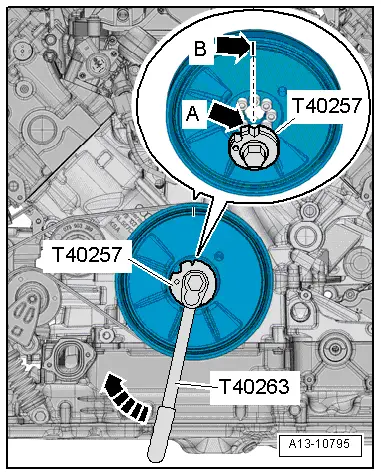
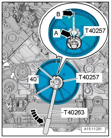
–  Fit adapter -T40257- onto wrench -T40263-.
–  Position adapter on bolts of vibration damper.
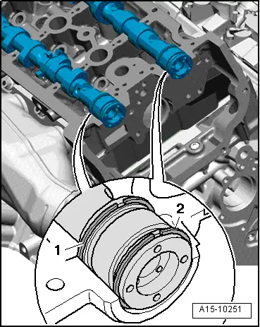
l  Notch -arrow A- on adapter -T40257- must point to coloured line -arrow B- on vibration damper.
  Note
Semi-circular recess on adapter -T40257- can be disregarded.
  Caution
Avoid damage to valves and piston crowns.
When performing the following steps, the crankshaft must not be at „TDC“ position at any cylinder.
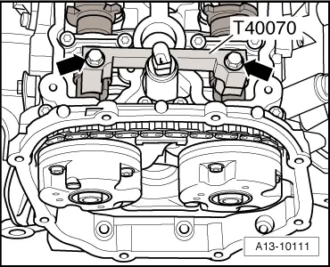
–  Using counterhold tool -T10172- with -T10172/7-, turn crankshaft back through 40° out of „TDC“ position in opposite direction to normal rotation -arrow-.
  A15-11201
–  Remove camshaft clamp -T40070--arrows-.
  A13-10111
–  Loosen and remove bolts for retaining frame in the sequence -24 ... 1-.
  Note
Perform the same procedure (laterally reversed) on retaining frame (right-side).
–  Carefully release retaining frame from bonded joint and detach.
–  Mark fitting location of camshafts for re-installation and remove.
Installing
l  Tightening torque → Fig. „„Retaining frame for camshafts - tightening torque and sequence““
  Note
t  Renew seals and gaskets.
t  Renew the bolts tightened with specified tightening angle.
  Caution
Protect lubrication system and bearings against contamination.
Cover exposed parts of the engine.
  WARNING
Protect eyes against injuries.
Wear safety goggles.
–  Remove remaining sealant from cylinder head and retaining frame using rotating plastic brush or similar.
–  Clean sealing surfaces; they must be free of oil and grease.
–  Oil running surfaces of both camshafts.
–  Insert camshafts in cylinder head; note position of camshafts to make sure retaining frame is fitted free of stress.
  A15-10225
Cylinder head (left-side):
1 - Inlet camshaft
2 - Exhaust camshaft
l  The groove on the end of the shaft must be positioned as shown in the illustration.
  A15-10250
Cylinder head (right-side):
1 - Exhaust camshaft
2 - Inlet camshaft
l  The groove on the end of the shaft must be positioned as shown in the illustration.
  A15-10252
Continuation for both sides:
–  Check position of ends of rectangular section seals.
l  The ends of the rectangular section seals -1 and 2- must point up or down, never to the side.
  Note
  A15-10251
Note the use-by date of the sealant.
–  Cut off nozzle of tube at front marking (nozzle Ø approx. 2 mm).
  A17-0081
–  Fit gasket -2- in grooves on retaining frame.
  Caution
Make sure excess sealant does not contaminate camshaft bearings.
The beads of sealant must not be thicker than specified.
–  Apply beads of sealant -1, 3, 4- onto clean sealing surfaces of retaining frame as shown in illustration.
l  Width of sealant beads: 2.5 mm.
  Note
The retaining frame must be installed within 5 minutes after applying the sealant.
–  Fit retaining frame onto cylinder head.
  Note
Make sure that camshafts can be inserted into axial bearing of retaining frame without applying force.
  A15-10215
–  Insert locating pins -T40116- in retaining frame and cylinder head.
  A15-10283
–  Tighten bolts for retaining frame → Fig..
  Note
After installing the retaining frame, the sealant must dry for approx. 30 minutes.
  A15-10225
–  Drive in sealing plugs -arrows- until flush.
  A10-10503
–  Use impact extractor attachment -T40116- to pull out locating pins -T10133/3-.
  A15-10284
–  Turn inlet camshaft to „TDC“ position; to do so, fit a socket (24 mm) -item 1- between inlet camshaft and camshaft adjuster bolt -2- and secure camshaft adjuster bolt to camshaft as shown in illustration.
  Note
Use pliers to counterhold socket when tightening bolt.
–  Apply lever or ratchet with special wrench -T10035- and turn camshaft until threaded hole for camshaft clamp -T40070- points upwards.
–  Initially screw bolt for camshaft clamp -T40070- only a few turns into inlet camshaft.
l  The camshaft clamp -T40070- is positioned correctly if the holes for the cylinder head bolts remain free.
  A15-10285
–  Fit camshaft adjuster bolt -2- and socket (24 mm) -item 1- onto exhaust camshaft.
–  Turn exhaust camshaft until threaded hole for camshaft clamp -T40070- points upwards.
–  At the same time apply open-end spanner (24 mm) to camshaft clamp -T40070- and pivot camshaft clamp -T40070- towards exhaust camshaft -arrow- until camshaft clamp can be fastened.
–  Secure camshaft clamp -T40070- to exhaust camshaft only hand-tight, to avoid damaging the thread (assistance of second mechanic required).
  A15-10253
–  Tighten bolts on camshaft clamp -T40070- to 25 Nm -arrows-.
  A13-10111
–  Rotate crankshaft in normal direction of rotation -arrow- to „TDC“.
  A13-10795
–  Screw locking pin -3242- into hole (20 Nm); if necessary, turn crankshaft -1- backwards and forwards slightly to fully centralise locking pin.
Remaining installation steps are carried out in reverse sequence; note the following:
–  Install high-pressure pump → Rep. gr.24.
–  Fit timing chains on camshafts → Anchor.
  Caution
Avoid damage to valves and piston crowns after working on valve gear.
t  The hydraulic tappets have to settle; wait for approx. 30 minutes after installing camshafts before starting engine.
t  Turn the engine carefully at least 2 rotations to ensure that none of the valves make contact when the starter is operated.
  A13-10046

Chain drive > < Cylinder head