audi Workshop Repair Guides

Audi Workshop Service and Repair Manuals

Securing engine to engine and gearbox support > < Removing engine
Separating engine and gearbox
Special tools and workshop equipment required
t  Support set for Audi -VAS 6131/10-, supplementary set -VAS 6131/11- and support -VAS 6131/13-7-
t  Adapter -T40257-
t  Socket -T40263-
t  Bolt M10x65
   
Procedure
l  Engine/gearbox assembly removed and secured to scissor-type assembly platform -VAS 6131 A-
–  Unbolt drive shaft (left and right) from gearbox flange shaft.
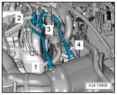
–  Detach electrical connectors from bracket, unplug connectors and move electrical wiring clear:
2 - For Lambda probe 2 -G108-
3 - For Lambda probe 2 -G131- (after catalytic converter)
  Note
Disregard -items 1, 4-.
  A24-10808
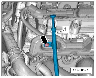
–  Remove bolt -arrow- and pull out guide tube -1- for oil dipstick.
  A17-10577
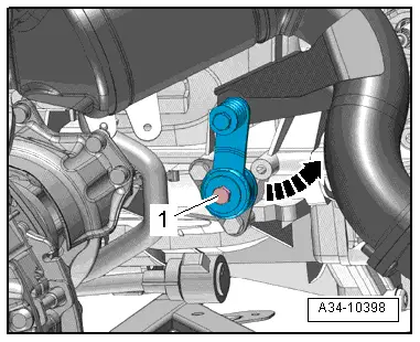
–  Remove bolt -1-, press bracket off gearbox and swivel to rear -arrow-.
  A34-10398
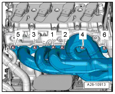
–  Remove nuts in the sequence -6 ... 1- and detach exhaust manifold with catalytic converter and front silencer (right-side).
  A26-10913
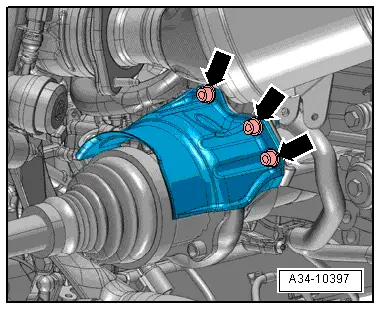
–  Remove bolts -arrows- and detach heat shield for drive shaft.
  A34-10397
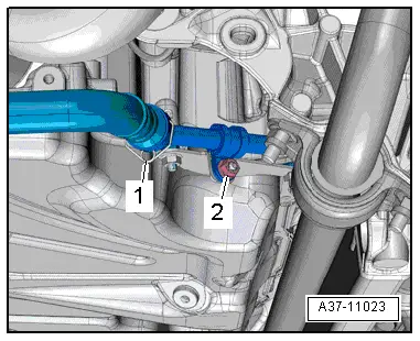
–  Remove nut -2-.
  Note
Disregard -item 1-.
  Note
Place a cloth underneath to catch escaping ATF.
  A37-11023
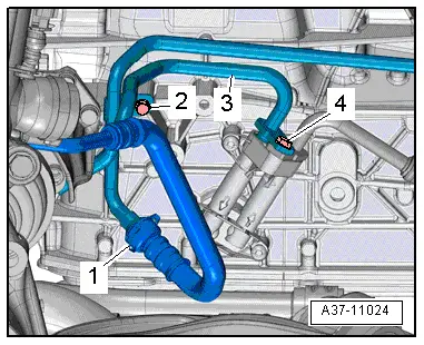
Vehicles up to 05.2010:
–  Detach clip -1- and disconnect ATF line.
–  Remove bolt -4-, detach ATF line -3- from gearbox and move to one side.
–  Seal off open pipes/lines and connections with clean plugs from engine bung set -VAS 6122-.
  Note
Disregard -item 2-.
  A37-11024
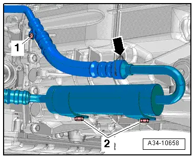
–  Remove bolt -1-.
  Note
Disregard -item 2- and -arrow-.
  A34-10658
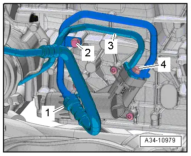
Vehicles from 06.2010 onwards:
–  Detach clip -1- and disconnect ATF line.
–  Remove bolt -4-, detach ATF line -3- from gearbox and move to one side.
–  Seal off open pipes/lines and connections with clean plugs from engine bung set -VAS 6122-.
  Note
Disregard -item 2-.
  A34-10979
All vehicles (continued):
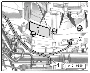
–  Unplug electrical connectors -1- for Servotronic solenoid valve -N119- and -2- at engine speed sender -G28- and move electrical wiring clear.
  A10-10869
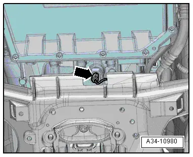
–  Unplug electrical connector -arrow- and move wiring clear.
  A34-10980
  Caution
Risk of irreparable damage to gearbox control unit (mechatronic unit) because of static discharge.
Do NOT touch connector contacts in gearbox connector with your hands.
–  Touch gearbox housing with your hand (without wearing gloves) to eliminate static charge.
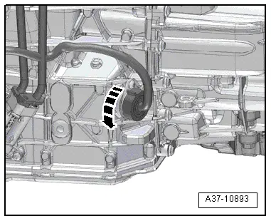
–  Turn retainer catch anti-clockwise -arrow- and unplug electrical connector at gearbox.
–  Move clear electrical wiring harness at gearbox.
  A37-10893
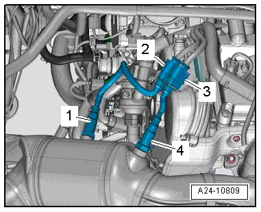
–  Detach electrical connectors from bracket and unplug.
2 - For Lambda probe after catalytic converter -G130-
3 - For Lambda probe -G39-
  Note
Disregard -items 1, 4-.
  A24-10809
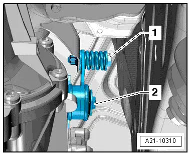
–  Remove bolt -2-.
  Note
Disregard -item 1-.
  A21-10310
–  Remove bolt -arrow-.
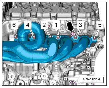
–  Remove nuts in the sequence -6 ... 1- and detach exhaust manifold with catalytic converter and front silencer (left-side).
  A26-10914
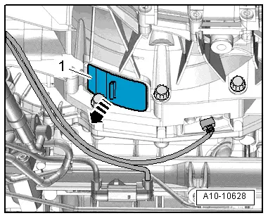
–  Detach bottom cover -1- from gearbox -arrow-.
  A10-10628
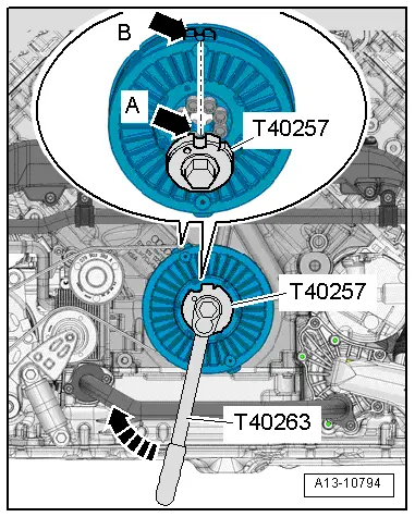
–  Fit adapter -T40257- onto wrench -T40263-.
–  Position adapter on bolts of vibration damper.
l  The semi-circular recess -arrow A- on the adapter -T40257- must point to the semi-circular recess -arrow B- on the vibration damper.
  Note
Disregard notch on adapter -T40257-.
–  Counterhold crankshaft using adapter -T40257- and wrench -T40263- when slackening bolts for clutch module.
  Note
When performing the next step, turn the crankshaft only in the normal direction of rotation -arrow-.
  A13-10794
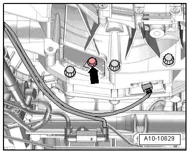
–  Remove 6 bolts -arrow- for clutch module, turning crankshaft 60° in normal direction of rotation each time.
  A10-10629
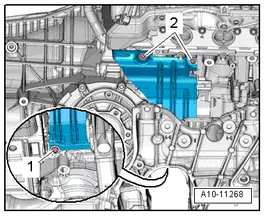
–  Remove bolt -1- and press heat shield for starter slightly to the side.
  Note
Disregard -item 2-.
  A10-11268
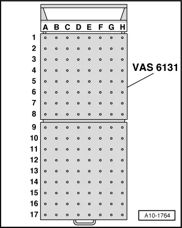
–  Set up scissor-type assembly platform -VAS 6131 A- with support set for Audi -VAS 6131/10-, supplementary set -VAS 6131/11- and support -VAS 6131/13-7- as follows:
  Note
The other support elements remain unchanged.
  A10-1764
Platform coordinatesParts from support set for Audi -VAS 6131/10-, support set -VAS 6131/11- and support -VAS 6131/13-7-
D2/13-7
C10/10-1/10-3/10-5/11-4
F10/10-1/10-3/10-5

   
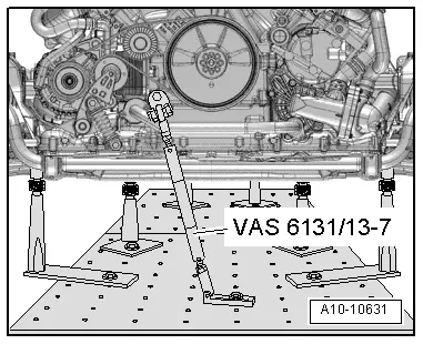
–  Secure support -VAS 6131/13-7- at tapped hole at front of engine (right-side) with bolt M10x65, as illustrated.
–  Secure support -VAS 6131/13-7- to scissor-type assembly platform and tighten to 20 Nm.
  A10-10631
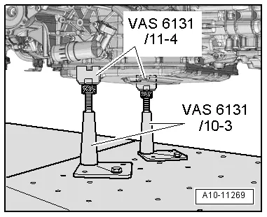
–  Position the support elements from -VAS 6131/10- and -VAS 6131/11- at front of gearbox, as shown in the illustration.
–  Screw spindles on both sides upwards until support elements -VAS 6131/11-4- make full contact with gearbox.
–  Tighten base plates for support elements to 20 Nm on scissor-type assembly platform -VAS 6131 A-.
  A10-11269
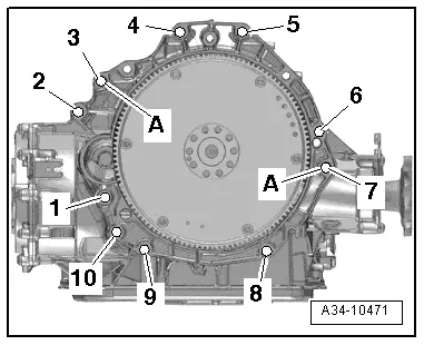
–  Remove bolts -1- and -2- for starter.
–  Separate starter from gearbox and leave in position.
–  Unscrew remaining bolts -3 ... 10- securing engine to gearbox.
  Note
Disregard -item A-.
  A34-10471
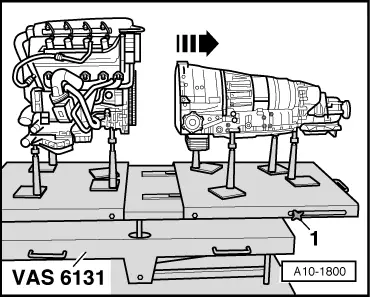
–  Loosen clamping bolts -1- on sides of scissor-type assembly platform -VAS 6131 A- and pull rear section of platform together with gearbox towards rear -arrow-.
  A10-1800

Securing engine to engine and gearbox support > < Removing engine