| t
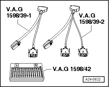
| The smaller of the two connectors on the engine control unit has the contacts 1 to 60. The larger of the two connectors has the contacts 1 to 94. |
| t
| The test box -V.A.G 1598/42- is designed so it can be connected both to the wiring harness for the engine control unit and to the engine control unit itself at the same time. |
| t
| The advantage of this is that the electronic engine control system remains fully functional when the test box is connected (for example, for measuring signals when the engine is running). |
| t
| The relevant test procedure will state whether it is necessary to also connect the engine control unit to the test box. |

WARNING | To prevent irreparable damage to the electronic components, select appropriate measuring range before connecting the measuring cables and observe the test requirements. |
|
| –
| The engine control unit has to be removed before multi-pin connectors can be unplugged from engine control unit → Chapter. |
| –
| Connect test box -V.A.G 1598/42- to wiring harness with adapter cable -V.A.G 1598/39-1- or adapter cable -V.A.G 1598/39-2-. Connect earth clip of test box to negative terminal of battery. The instructions for performing the individual tests indicate whether or not the engine control unit itself also needs to be connected to the test box. |
| –
| Carry out test as described in appropriate repair procedures. |
| Installing engine control unit |
| Installation is performed in the reverse sequence. |
| –
| After installation, the protective housing must be re-fitted on the control unit. |
| –
| Clean threaded holes for shear bolts to remove any residue from locking fluid. This can be done using a thread tap. |
| –
| Always use new shear bolts. |
| The procedure required after connecting the new engine control unit is described in the Guided Fault Finding or Guided Functions. |

Note | After completion of the Guided Fault Finding routine, the tester will attempt to erase the event memories of all control units. If this is not successful, the remaining faults registered in the memories must be rectified until all fault entries can be erased. |
|
|
|
